Appendix G: Menu Structure Quick Reference
66 Siemens Power Transmission & Distribution,Inc.
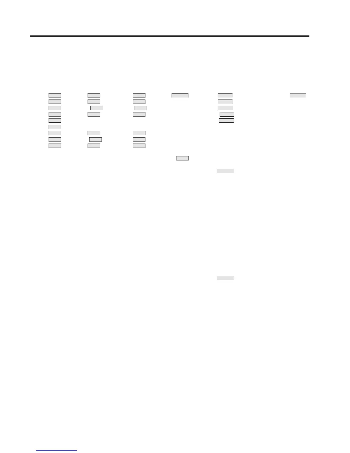
G.2 MJ-X
L
Menu Structure
Table G.1 MJ-X
L
Menu structure part 1
<METER> <FW DEMAND> <REV DEMAND> <COUNTERS> <REGULATOR> <CONFIGURE> <ALERTS>
Vld F Dmd Vld R Dmd Vld Total Ops Fwd Volts Tap Chngr 1st Alert
Vs F Dmd Vs R Dmd Vs Reset Date Fwd BW Type ...
Vcomp FDmd Vcomp RDmd Vcomp Reset time Fwd Delay Syst Last Alert
Ild F Dmd Ild R Dmd Ild Elapsed Ops Fwd Comp(R) DeltaPwr
PF PFKVA max PFKVA max 24 Hr Ops Fwd Comp(X) Utility Pol Alerts:
KVA PFKVA min PFKVA min 30 Day Ops U2 PT Low current
KW F Dmd KW R Dmd KW MTD Ops Rev Volts P2 PT Auto inhibit
KVAR F Dmd KVAR R Dmd KVAR Last Month Ops Rev BW CT ratio Tap track error
Freq F Dmd KVA R Dmd KVA YTD Ops Rev Delay Meter Volts Neutral sig. err.
KWHR F Last Year Ops Rev Comp(R) I Threshold % Tap position???
KVAR HR F lead Tap position Rev Comp(X) I Shift Low PT Thresh
KVAR HR F lag Alt Delay I Load Max Overcurrent
KWHR R VRC Stat I Full Load NV RAM Reset
KVAR HR R lead VRC1 In Pwr Flow (mode) Low Battery
KVAR HR R lag VRC2 In PT Threshold High Voltage
VRC Mode Time Not in Auto
Local VRC% Date R Limit Reached
Format (Date) L Limit Reached
VRC Stage 1 Dmd Type Pseudo Manual
VRC Stage 2 Dmd Time
VRC Stage 3 Dmd Subperiods
VRC Remote Reset Min/Max?
MJ-3A VRC% Min/Max t.o.
Screen t.o.
AutoVRCset1 Function t.o.
AutoVRCset2 Basis Volts
AutoVRC1 %I R Limit
AutoVRC2 %I L Limit
TapAlert
VLC Enable TapPosHold
VLC Upper Version
VLC Lower Memo 1
Memo 2
Max/Min Max/Min Max/Min Op Counter Volt Level
Alert Status
Max/Min Max/Min Max/Min Bandwidth
Max/Min Max/Min Max/Min Time Dela
Max/Min Max/Min Max/Min Resistance
Max/Min Reactance
Max/Min
Max/Min Max/Min Max/Min
Max/Min Max/Min Max/Min
Max/Min Max/Min Max/Min
Max/Min
VRC Select
VLC Select

 Loading...


