4 Setting Up the MJ-XL Control Panel
Siemens Power Transmission & Distribution, Inc. 17
Note: Depending upon the version of software in
your MJ-X
L
Control Panel, your menus may be
slightly different than those described. If your
control panel does not support all of the fea-
tures described, please contact your Siemens
representative for details about obtaining the
latest version of the software.
4.2 Setup for Retrofit Panels
If you are retrofitting either a G. E. or Cooper regulator for
use with the Siemens MJ-X
L
Control Panel, please refer to
the respective Application Note. Contact your Siemens
representative for details.
4.3 Defining Your Regulator—
the <CONFIGURE> Menu
When the MJ-X
L
Control Panel is delivered pre-installed on
a regulator, many of the configuration variables are already
set. However, the MJ-X
L
Control Panel provides a wide
range of additional variables that can be used to make the
regulator perform more effectively in your system.
Variables in the <CONFIGURE> Menu are summarized in
Table 4.1 and explained in the following pages.
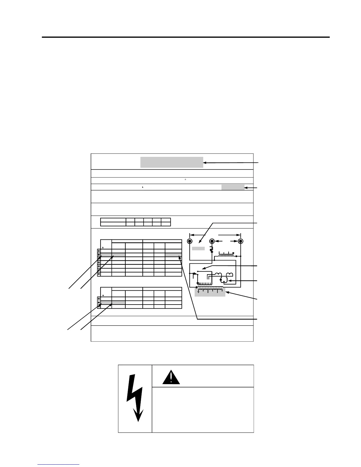
Figures 4.1 to 4.3 show typical Siemens regulator name-
plates. Refer to these figures for information that can be
obtained from Siemens regulator nameplates.
Figure 4.1 Typical Siemens Regulator Nameplate for older ANSI Type B (Inverted) Regulator
(Regulator type not identified on nameplate)
Note: Items are not highlighted on actual nameplate.
SIEMENS
5/8% Step-Voltage Regulator Serial No.
Single Phase Type JFR 60 Hz 55 C Rise 95 BIL Class 0A
76.2 kVA 7620 volts 10% in 32 - 5/8% Steps
100 Amps
Insulating Fluid :
Fluid PCB content :
ASTM D-3487 Type II Mineral Oil
Less than 1 ppm at time of manufacture
Untanking Hgt = 114 in.
Untanking Wgt = 937 lbs.
Oil = 62 gals
Total Wgt = 1598 lbs.
* Control diag :
Nameplate :
Forward Power Flow - Connect Load Side
Reverse Power Flow - Connect Source Side
Voltage Transformer per Table 1.
Voltage Transformer per Table 2.
% Regulation
Max Amps 100 110 120 135 160
10 8 7
3/4 1/2 1/4
6 5
Load
Volts
10%
Source
Volts
10%
8000
8000
7620
7620
7200
7200
6930
5000
4330
2500
127 V
120 V
121 V
120 V
123 V
120 V
118 V
124 V
125 V
121 V
P2-P3
P12-P13
P2-P3
P12-P14
P2-P4
P12-P15
P2-P4
P2-P5
P2-P6
P2-P7
20
20
20
20
20
20
23
21
20
25
27
20
20
20
21
23
21
20
20
21
120 V
120 V
120 V
120 V
120 V
120 V
120 V
125 V
125 V
125 V
Control & Motor
Control & Motor
Control Panel Conn
Control Panel Conn
Volts
E-P2
Volts
E-P12
Connect
*
Connect
*
PA
to
PB
to
P14A
to
P14B
to
Control
Volts
Control
Volts
Aluminum conductor in shunt winding.
Aluminum conductor in series winding.
Do not by-pass unless on neutral and control switch on panel is off
See instruction book before placing in service.
CTsec conn C2 to C3
Siemens Po w er Transm issio n & Ditributio n, I nc.
Jacks o n, MS
Made in U S A
21-115905-002
P7
P6
P5
P13
P4
P14
P3
P15
E2
E3
E1
CT
AMPS
100 : 0.2
C3
123456
A B
M
K
S
LOAD
L
SL
SOU RCE
0 78
CTratio 100:0.2
I FullLoad 100
TapChngr SIEMENS
Basis volts 120
Utility Pol NORM
(E2 to right of P terminals
Tap Changer
Preventive
Autotransformer
Tap Changer
Reversing Switch
U2PT: 7620:121
P2PT: 7620:120
CAUTION
To prevent minor or moderate injury
including damage to the regulator or
control components: use the example
diagrams only for illustration purposes.
Refer to the regulator nameplate for the
proper control diagram to use with a
particular installation.

 Loading...


