4 Setting Up the MJ-XL Control Panel
Siemens Power Transmission & Distribution, Inc. 31
Note 3, Collecting MJ-X Data with a (Cooper) Data Reader
[Using the DRIP].)
To set the Communications unit address, view Comm
Addr under the <COMMUNICATIONS> Menu. Enter the
desired address.
The “Comm Addr” screen shows the communications
address for the MJ-X
L
unit. For the Data Port, the usable
address ranges are listed in Table 4.8 below. Note that the
MJ-X
L
is device type “1”, and its group address is 254.
4.7.2 Using the Communications Module
The MJ-X
L
Communications Module provides remote
communications capability for the MJ-X
L
Control Panel.
The Communications Module is a plug-in option offering
choices of communications protocols and physical inter-
faces. Since the MJ-X
L
Communications Module Installa-
tion Manual describes the configuration items in detail,
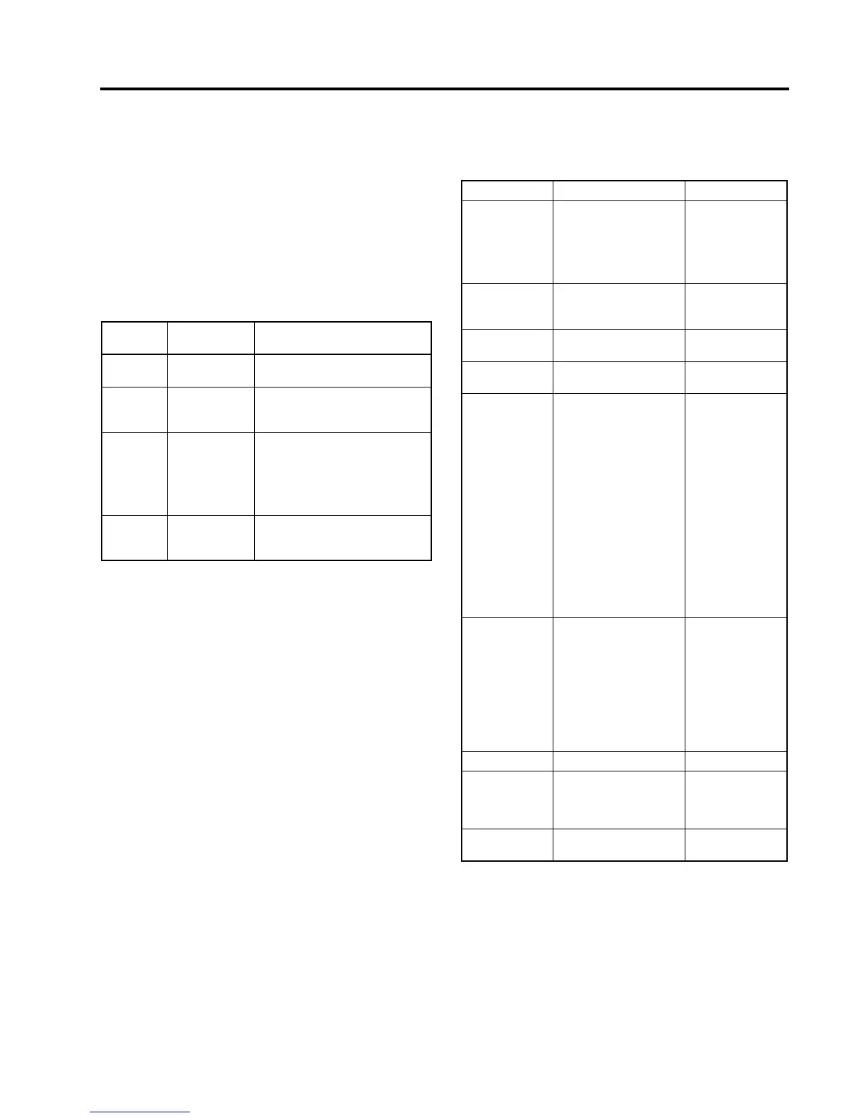
they are listed only for reference in Table 4.9
Note: Default values shown in bold type.
Note: If both the Data Port and the Communications
Module are simultaneously set up for remote
communications, then the Data Port restric-
tions on the value of the “Comm Addr” data
item must apply.
* See Comm Module Instruction Manual for limitations
on 19,200 baud.
Table 4.8 Data Port Addresses
Address
Range
Function How Used
0 Wild Card
Address
All controls on system respond.
1 to 200 Unique Device
Address
When an address in this range is
sent, only the control that has
that unique address responds.
201 to 254 Device Type,
Group
Address
Any control with the correspond-
ing group address (which is
determined by the control’s
device type) receive and execute
commands with no return
response.
255 Broadcast
Address
All controls on the system
receive and execute commands,
with no return response.
Table 4.9 Communications Module Configuration Items
DATA ITEM DESCRIPTION SELECTIONS
Protocol: Communications
Module Protocol
DNP3.0, 2200,
2200NOA,
MJ3A A,
MJ3A B1,
MJ3A B2, 2179,
and Special
Comm Baud: Communications
Module transmission
rate
300, 1200, 2400,
4800, 9600, or
19,200*
Comm Parity: Communications
Module Parity
NONE, EVEN,
ODD
Comm Addr: Communications
Module Address
NNNNN
(range: 0 - 32765)
Resync Time: Communications
Module resync time (in
characters). Used for
Communications Mod-
ule protocols 2200 and
2179 to determine
when one message
ends and another mes-
sage begins. If a new
character is not
received within the
period specified by this
parameter, the control
panel assumes that the
next received character
is the start of a new
message.
NNN
(range 0-250,
1)
Tx En Delay: Communications
Module Transmit
Enable Delay (in
milliseconds).
Specifies the amount of
time between the RTS
output being
activated and the start
of transmit (output)
data.
NNN
(range 0-250)
DNP dl Confirm DNP Data Link Confirm Y or N
CM SW
RepeatEn
Enable software auto-
repeat in Comm
Module (MJ-3A
protocol only)
Y or N
CM Vers Comm Module soft-
ware version
N.NNNN

 Loading...


