Appendix D: Menu Parameters
Siemens Power Transmission & Distribution, Inc. 61
EXAMPLE 1 (ref: Table D.3)
In Figure D.3 below, U6 is to the left of E2. If your regula-
tor nameplate looks like this, the proper specification is
Utility Pol:NORM.
Figure D.3 U6 to the Left of E2
EXAMPLE 2 (ref: Table D.3)
In Figure D.4 below, U6 is to the right of E2. If your regula-
tor nameplate looks like this, the proper specification is
Utility Pol:REV.
Figure D.4 U6 to the Right of E2
D.3.2 Three-Phase Regulators
Three-phase regulators may have either one or multiple
utility windings.
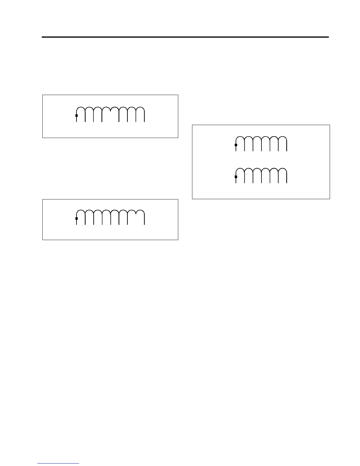
D.3.2.1 Single Utility Winding
A single utility winding provides power for the control, the
motor and the cooling fan. This utility winding may have
the polarity mark at the Un — Ux terminals or at the U5
terminal, as shown in the examples of Figure D.5.
Figure D.5 Three-Phase Regulator with a Single Utility
Winding
To determine whether the polarity is ‘Normal’ or ‘Reverse,’
examine the connection table and schematic diagram.
• If U2 is connected to a “U” terminal which is to the
left of E2, then UtilityPol:NORM (see Figure D.6).
• If U2 is connected to a “U” terminal which is to the
right of E2, then UtilityPol:REV (see Figure D.7).
U3
E2
U

 Loading...


