Service Manual
Installation Instructions
Siemens Ltd. Med Division India Version 4.0
Page 6 of 12
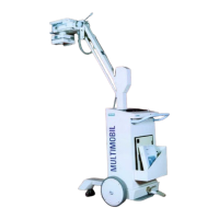
1.6 Transport and Positioning of Unit
Refer corresponding section on Transporting the Unit and Positioning for Exposures in
the Operating Instructions.
1.7 Preliminary Check :
1.7.1 Mains :
1. Check available mains voltage at the site either 110 V or 230 V AC.
2. Check if the mains voltage is between 99 V to 121 V ac or 180 Vac to 265 Vac
respectively.
3. The unit is set for respective line voltage at the time of despatch from factory.
5. When the mains voltage is less than 205V on 230 V ac line, than the LN contactor
is energised for line condition compensation circuit.
6.Check if the mains resistance is < 1.2 Ω.
1.7.2 Interconnections
Type Description Specifications
Mains
1 Mains Cable 3 x 1.5 sq.mm
Control - single Tank
Control Single Tank
D915.X8, X1 Connector 3 Core shielded PVC insulated, kV/mA feedback
Cable
D801.X60 Allied Connector 2 Core 1 mm sq. Grey, Collimator Cable
D801.X5 11/12 - D900A 2 Core shielded PVC insulated, Filament cables
11 & I2
D801.X3 0,I,II - D900A 3 Core shielded PVC insulated , Anode Rotation
cable.
D960 (out1) and
capacitor C6
U,V - D900A 6 mm sq. Black U & V Cables
Earthing terminal Earthing stud 6 mm sq Yel/Green Earth Cable
Interconnections
D915.X11 to D801.X11 Flat Band 16 core.
D915.X10 to D801.X10 Flat Band 26 Core.
D915.J24 to D932.X1 Flat Band 28 Core.
D915.X20 to D960.X20 to D950A .X20 Flat Band 20 Core.
D915.X12 to D936.X12 Flat Band 14 Core.
D915.X15 to D980.X15 Flat bonded cable K7
D801.X9 to D980 .X9 SMPS Mains cable K12
Wire bunch to D801.X1 10 pin molex connector
Wire bunch to D801.X50 3 pin molex connector
Wire bunch to D801.X18 6 pin molex connector
Contactor CS to X3.D950A Charger cable S4 with 6 pin connector
Bleeder resistor to X9.D950A 3 pin connector discharge cable
The max. Permissible resistance between the earthing terminal in the control and the
single tank is less than 0.2 ohms.

 Loading...