Service Manual
Installation Instructions
Siemens Ltd. Med Division India Version 4.0
Page 8 of 12
In case of any errors while setting up / hardware check / stand-by operation, the
corresponding Error code will be displayed on the same displays.
e.g. The display will indicate Error 99 in case the unit while setting up/ after setup
detects that last reset of the unit was due to watch-dog timer RESET.
Note: The Control Unit contains Non volatile Memory which retains the last
selected kV and mAs. So the initial display after setup will depend on the last
settings done.
If the unit is being installed after six months from the date of despatch then the
forming for the Capacitors is a must.
2.1 Forming of the Capacitor Bank:
Open the top panel cover of MM10 control by removing the ornamental screws (2x)
and put the ST link (jumper pin) on D915 PCB.
Switch ON the MCB
.
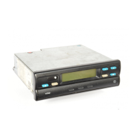
Switch the Generator ON by actuating momentarily
Then the kV and mAs display read as shown in picture, if there are no initialisation
Errors.
MCB

 Loading...