Operating the double-busbar system
100 NXAIR M 139-2021.9 / 07
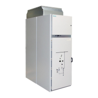
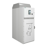
Fig. 162: Control elements on the panel front of the
circuit-breaker panel for double-busbar
system, panel B
Door to the low-voltage compartment
Locking device for the door to the low-voltage
compartment
Test sockets for voltage detecting system
(type LRM) for the busbars as additional
component
Instruction label for closing the
high-voltage door
Opening for charging the spring in the circuit-
breaker manually (covered)
Handle for opening the high-voltage door
Control gate for opening and closing the
actuating opening for racking the switching
device
Actuating opening for racking the switching
device
Actuating opening for inserting the double-bit
key to control racking of the withdrawable part
Mechanical position indicator for withdrawable
part
Operations counter for circuit-breaker
Spring state indicator for circuit-breaker
CLOSED/OPEN indicator of the circuit-breaker
Actuating opening for opening the circuit-
breaker
Actuating opening for closing the circuit-
breaker
Rotary button to close and open the actuating
opening located below

 Loading...


