EasyManua.ls Logo

Siemens NXAIR M - Basic Design Circuit-Breaker Panel, Double-Busbar System

Siemens NXAIR M
255 pages
To Next Page IconTo Next Page
To Previous Page IconTo Previous Page
Loading...
Panel design
139-2021.9 / 07 NXAIR M 19
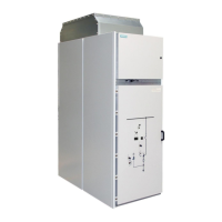
6.3 Basic design circuit-breaker panel, double-busbar system
Fig. 18: Sectional view of circuit-breaker panel design
A
Switching-device compartment
B
Busbar compartment
C
Connection compartment
D
Withdrawable circuit-breaker
E
Low-voltage compartment
(1)
Panel A
(2)
Metallic shutters
(3)
Low-voltage connection
(4)
Operating and interlocking unit for circuit-breaker
(5)
Vacuum interrupters
(6)
Operating and interlocking unit for racking the
withdrawable part and for earthing
(7)
Feeder earthing switch
(8)
Connection for up to 4 cables per phase
(9)
Block-type current transformers
(10)
Contact system
(11)
Voltage transformers
(12)
Bushing-type insulators
(13)
Busbars
(14)
Pressure relief duct
(15)
Panel B
Further information to design features and design options is given in catalog HA 25.71.
8
7
1
2
3
4
5
6
9
10
11
12
13
14
15

Table of Contents

Related product manuals