5
Mounting / Installation
Detector heating unit FDBH291
46
Building Technologies A6V10316298_e_en_--
Fire Safety 2014-05-21
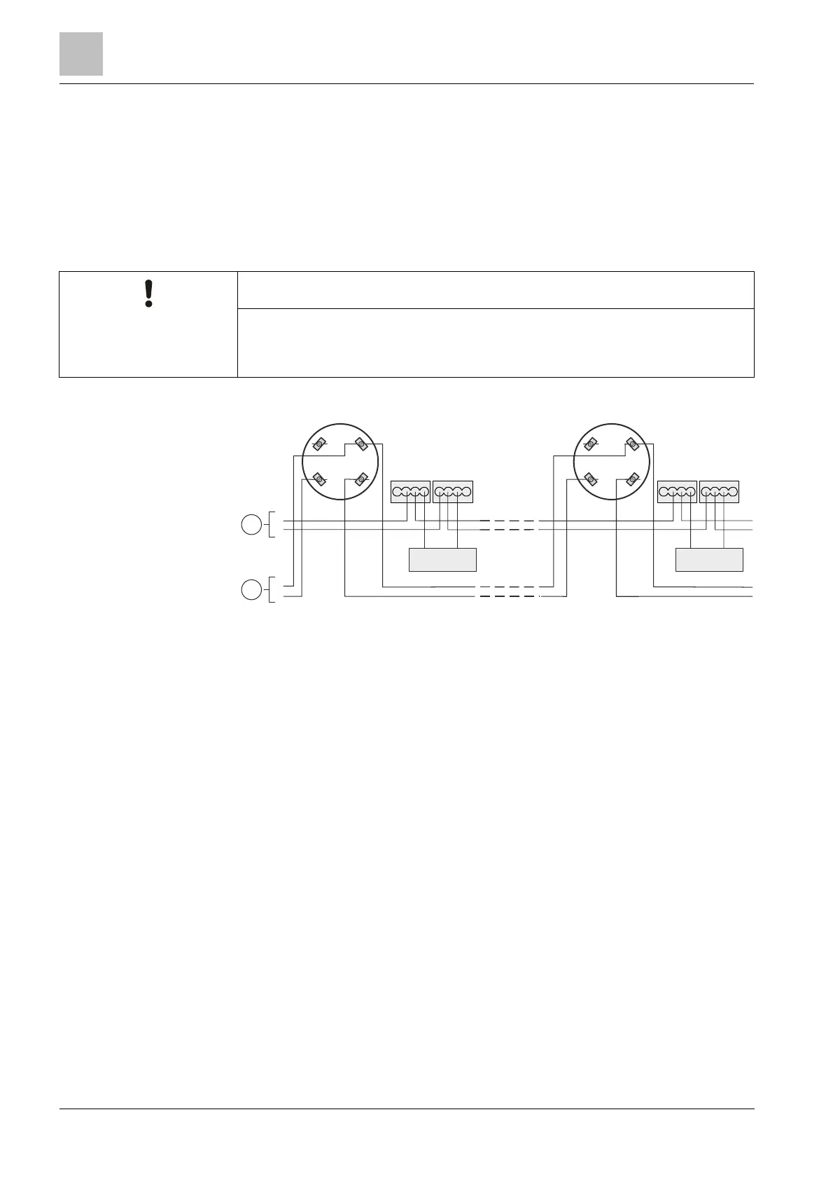
5.10.2 Connection of the detector heating unit
l Connect the cables for the monitored supply from the control panel and the
detector heating unit to the supplied micro terminals DBZ1190-AA.
l The cables can be placed in the same cable harness as the detector line or
separately.
l Several detector heating units can be connected in parallel.
l Detector heating units require a separate supply.
NOTICE
Malfunction
To ensure smooth operation, the detector must be checked regularly for icing.
+
DBZ1190-AA
-
+
LINE
FDBH291
-
+
1
2
-
+
1a 1b
5 6
1a 1b
5 6
+
DB721
Connection diagram for detector heating unit FDBH291
1
Control panel supply (monitored)
2 Control panel
 Loading...