Product Characteristics
4.2 Installation
SIMATIC NET PROFIBUS, Optical Link Module
Operating Instructions, 07/2008, A2B00065774O, Edition V1.5
23
The significance of the DIL switches of the OLM when S7=1 for:
SINEC L2FO
OLM/P3 and OLM/P4
SINEC L2FO
OLM/S3 and OLM/S4,
OLM/S3-1300 and OLM/S4-1300
S6 Output power CH4 S6 Reserved
0
1
Standard
High
S5 Output power CH3 S5 Reserved
0
1
Standard
High
S4 Reserved S4 Reserved
S3 Reserved S3 Distance
0
1
Extended
Standard
S2 Redundancy S2 Redundancy
0
1
Off
On
0
1
Off
On
S1 Mode Monitor S1 Mode Monitor
0
1
Line/ring
Line
On
Off
0
1
Line/Ring
Line
On
Off
S0 Reserved S0 Reserved
S8 Reserved S8 Reserved
OLM/P3: S6 reserved OLM/S3, OLM/S3-1300: S2 reserved
Table 4-2 DIL-switches in compatibility mode
4.2.3.2 Setting the mode
Notice! The following information is only valid for the default setting of S7 (S7 = 0),
this means compatibility is disabled!
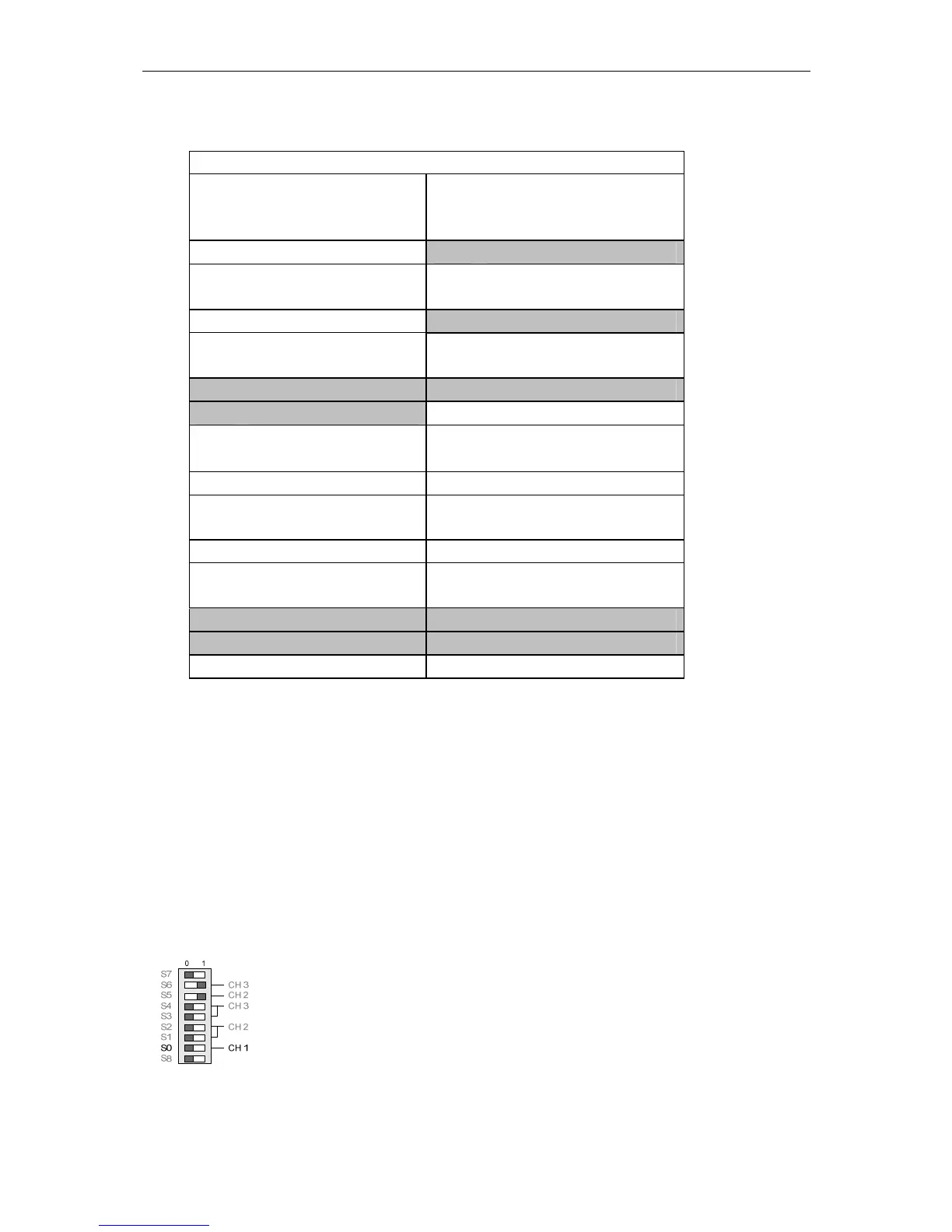
The mode of the electrical channel CH1 is set with DIL switch S0. The mode of
optical channel CH2 is set with DIL switches S1 and S2. The mode of optical
channel CH3 is set with DIL switches S3 and S4. If the OLM has only one optical
interface, S3 and S4 have no function.
4.2.3.3 Setting the mode of the electrical channel (CH1)
Mode “electrical channel with segment monitoring“
CH1 is set to this mode, when S0 is in position 0.
 Loading...