Installation and Maintenance
5.3 Connection of the Electrical RS-485 Bus Cables
SIMATIC NET PROFIBUS, Optical Link Module
Operating Instructions, 07/2008, A2B00065774O, Edition V1.5
33
The modules are equipped with an electrical port with RS-485
level. It is designed as 9-pin D-sub jack with screw locking
mechanism (inner thread UNC 4-40).
The pin assignment corresponds to the PROFIBUS standard
assignment. A short-circuit proof 5 V output for the supply of
external pull-up/pull-down resistances is available at pin 6. The
resistances must have a power loss of at least 0.25 W. The RS-
485 bus cables RxD/TxD, N and RxD/TxD, P are galvanically
isolated from the 24 V supply voltage within the SELV limits
(functional isolation).
The RS-485 interface is electrically connected with the housing.
71
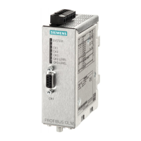
10,15 37,350 60,15
108
0
21,7
67,883,3
3x Ø3,5
Figure 5-6 Drilling measures for the mounting plate, all dimensions are millimeter
5.3 Connection of the Electrical RS-485 Bus Cables
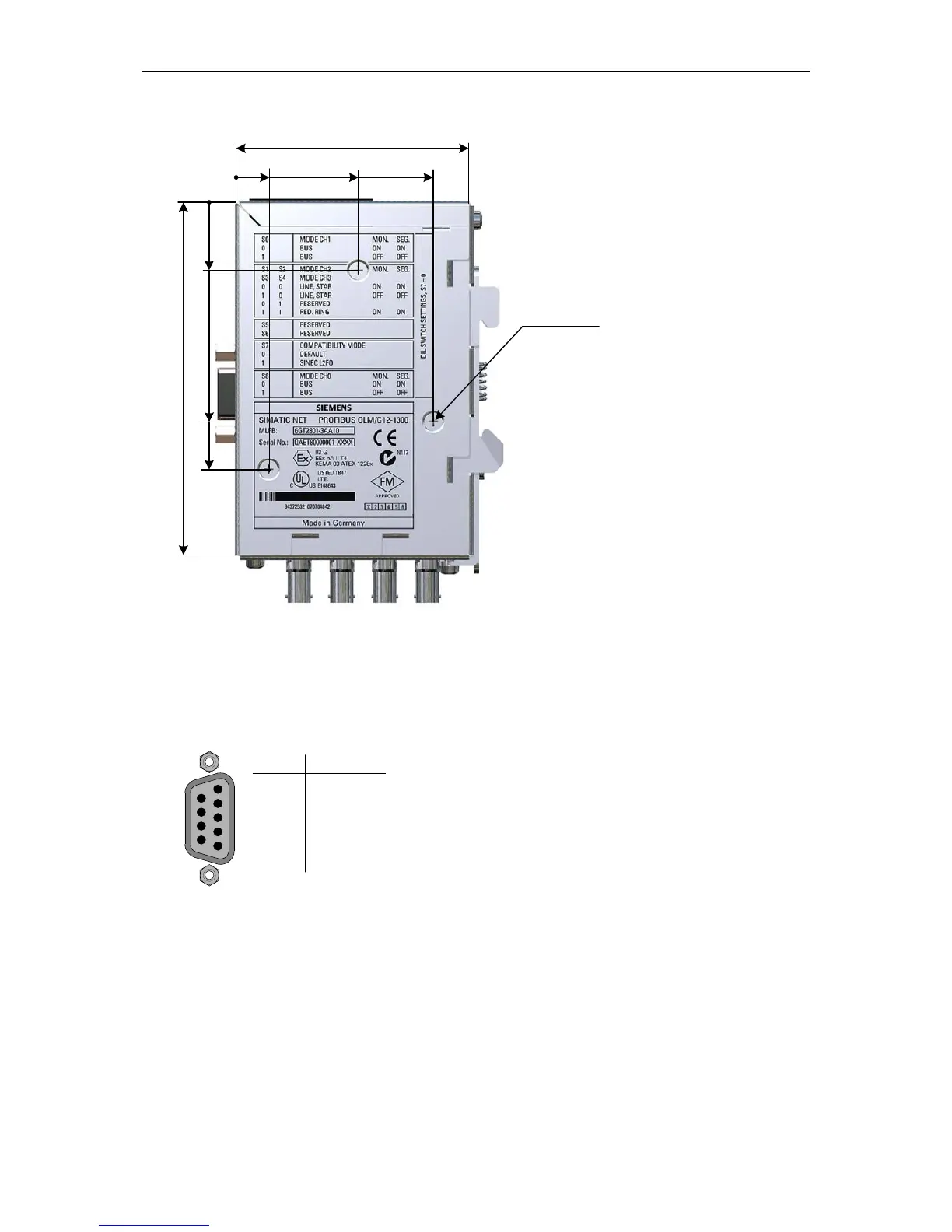
Figure 5-7 Electrical port, connector
assignment D-sub jack
RxD/TxD, P
RxD/TxD, N
Ground
+5V Output
RTS
vacant
5
4
3
2
1
9
8
7
6
3
8
5
6
4
1, 2, 7, 9
Assignment
Pin
 Loading...