Installation and Maintenance
5.2 Installation of the Modules
SIMATIC NET PROFIBUS, Optical Link Module
32 Operating Instructions, 07/2008, A2B00065774O, Edition V1.5
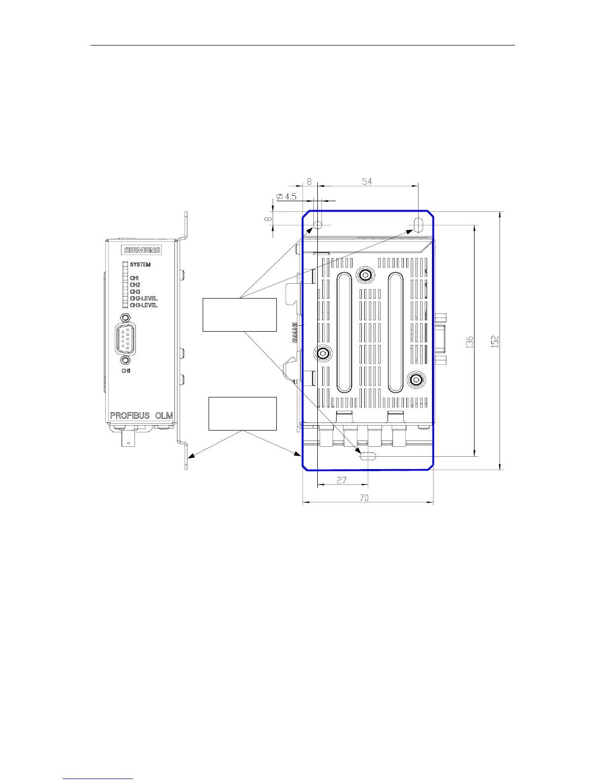
Installation on a mounting plate
¾ Unscrew the 3 screws on the right side of the OLM (the side with the type label).
¾ Fix with this screws the mounting plate (MLFB: 6GK1503-8AA00).
¾ Now fix the OLM at the wall or at a cubicle plate.
¾ Make sure there is a reliable and permanent electrical connection between the mounting plate and
surface, for example by using toothed washers.
mounting plate with
OLM on the front
holes for wall (plate)
installation
Figure 5-5 Installation of a module with a mounting plate
 Loading...