Network Topologies
3.3 Ring Topology
SIMATIC NET PROFIBUS, Optical Link Module
14 Operating Instructions, 07/2008, A2B00065774O, Edition V1.5
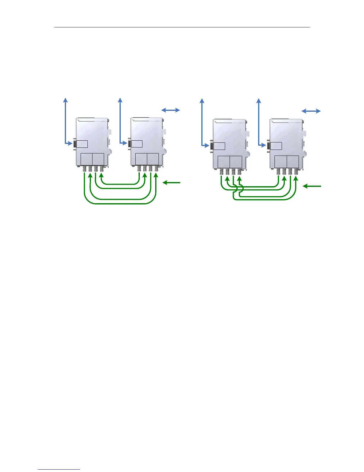
3.3.1 Redundant Optical Ring with two OLMs
Setting up a redundant optical ring with two PROFIBUS OLMs can be seen as
special case of the redundant optical ring and can be implemented with the
following two configurations.
How the LEDs react in the redundant optical ring:
A frame received by any channel is passed on to all other channels. If the frame
was received at an optical channel, it will also be sent back to the sender on the
same channel as an echo and therefore serves as a monitoring frame to test the
fiber-optic links between the OLMs.
The OLM recognizes whether a received frame is an echo or a frame that was
forwarded. In the case of an echo frame, the channel LED stays off whereas in the
case of a forwarded frame it will light up yellow. In networks with more than two
OLMs, echo frames and forwarded frames will alternate quickly. Due to the
extended display-time of at least 300 ms, all channel LEDs seem to be lit yellow
continuously.
The channel LEDs may react differently in the redundant optical ring only if the
following conditions are met:
1. The redundant optical ring consists of exactly two OLMs and the two fiber-optic
links are of different length (difference > approx. 2 m).
Under these conditions, the receiving OLM will always receive a sent frame first on
the channel with the shorter fiber-optic link. The channel signals this with a lit
yellow LED. The frame on the other optical channel is interpreted as an “echo
frame”, the channel LED stays unlit. Since the fiber-optic cable lengths represent
static variables, the display reaction is also static.
Ch 1
Ch 2
SE
Ch 3
SE
OLM/P12
OLM/G12(-1300)
Ch 1
Ch 2
SE
Ch 3
SE
OLM/P12
OLM/G12(-1300)
DTE/
bus segment
DTE/
bus segment
FOC
RS-485
Ch 1
Ch 2
SE
Ch 3
SE
OLM/P12
OLM/G12(-1300)
Ch 1
Ch 2
SE
Ch 3
SE
OLM/P12
OLM/G12(-1300)
DTE/
bus segment
DTE/
bus segment
FOC
RS-485
Figure 3-2 Configuration 1 Figure 3-1 Configuration 2
 Loading...