Network Topologies
3.3 Ring Topology
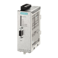
SIMATIC NET PROFIBUS, Optical Link Module
Operating Instructions, 07/2008, A2B00065774O, Edition V1.5
15
¾ Configuration 1 (see Figure 3-2 Configuration 1, FOC1 < FOC2) , LED display:
1. Situation, no FOC interruption:
OLM 1 OLM 2
SystemLED = lit green SystemLED = lit green
CH1 LED = lit yellow CH1 LED = lit yellow
CH2 LED = lit yellow CH2 LED = is not lit
CH3 LED = is not lit CH3 LED = lit yellow
2. Fault, FOC1 interrupted:
OLM 1 OLM 2
System
LED = lit green
SystemLED = lit green
CH1 LED = lit yellow CH1 LED = lit yellow
CH2 LED = lit red CH2 LED = lit yellow
CH3 LED = lit yellow CH3 LED = lit red
3. Fault, FOC2 interrupted:
OLM 1 OLM 2
System
LED = lit green
SystemLED = lit green
CH1 LED = lit yellow CH1 LED = lit yellow
CH2 LED = lit yellow CH2 LED = lit red
CH3 LED = lit red CH3 LED = lit yellow
¾ Configuration 2 (see Figure 3-1 Configuration 2, FOC1 < FOC2) , LED display:
1. Situation, no FOC interruption:
OLM 1 OLM 2
SystemLED = lit green SystemLED = lit green
CH1 LED = lit yellow CH1 LED = lit yellow
CH2 LED = lit yellow CH2 LED = lit yellow
CH3 LED = is not lit CH3 LED = is not lit
2. Fault, FOC1 interrupted:
OLM 1 OLM 2
SystemLED = lit green SystemLED = lit green
CH1 LED = lit yellow CH1 LED = lit yellow
CH2 LED = lit red CH2 LED = lit red
CH3 LED = lit yellow CH3 LED = lit yellow
 Loading...