Network Topologies
3.3 Ring Topology
SIMATIC NET PROFIBUS, Optical Link Module
16 Operating Instructions, 07/2008, A2B00065774O, Edition V1.5
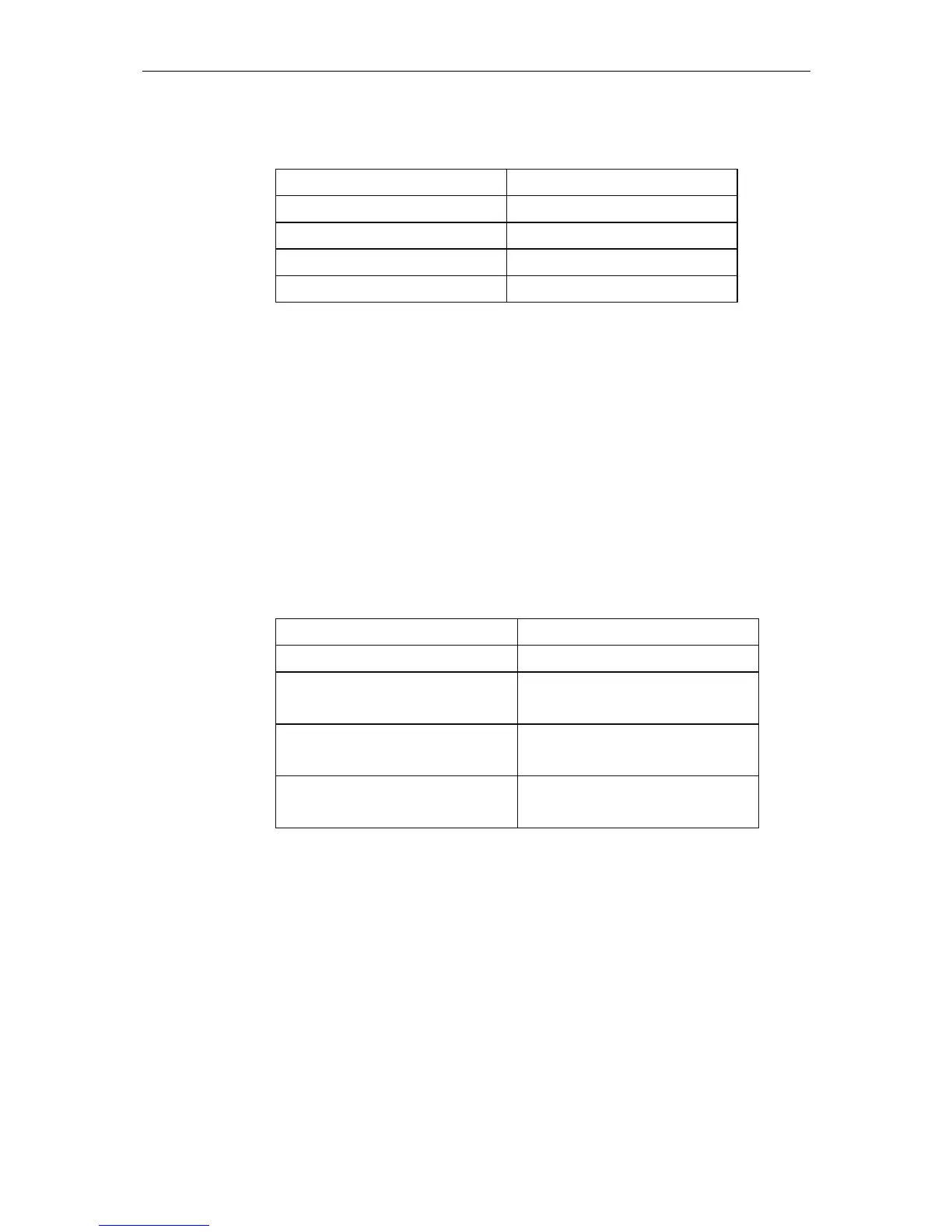
3. Fault, FOC2 interrupted:
OLM 1 OLM 2
SystemLED = lit green SystemLED = lit green
CH1 LED = lit yellow CH1 LED = lit yellow
CH2 LED = lit yellow CH2 LED = lit yellow
CH3 LED = lit red CH3 LED = lit red
2. The redundant optical ring consists of exactly two OLMs and both fiber-optic
cable connections are of exactly the same length.
Under these circumstances, that the receiving OLM receives a frame on both of the
optical channels at the same time. To manage this case, the OLM prioritizes the
two optical channels. By definition, the frame on one optical channel will then be
taken as an echo (channel LED = off) and the frame on the other optical channel
will then be taken as a forwarded frame (channel LED = yellow).
Due to the effect of jitter and the resulting sampling differences between the two
optical input channels, it is possible that one or the other optical channel receives a
frame first. Due to the extended display time of at least 300 ms. all channel LEDs
are then lit yellow continuously.
¾ Configuration 1/2 (FOC1 = FOC2), LED display A:
1. Situation, no FOC interruption:
OLM 1 OLM 2
SystemLED = lit green SystemLED = lit green
CH1 LED = lit yellow CH1 LED = lit yellow
(continuous, flashing, flickering) (continuous, flashing, flickering)
CH2 LED = lit yellow CH2 LED = lit yellow
(continuous, flashing, flickering) (continuous, flashing, flickering)
CH3 LED = lit yellow CH3 LED = lit yellow
(continuous, flashing, flickering) (continuous, flashing, flickering)
2. Fault, FOC1 interrupted:
see above
3. Fault, FOC2 interrupted:
see above
Generally:
Regardless of whether a channel LED is lit or not, all optical channels are
monitored continuously in the redundant optical ring. If a channel LED is not lit, the
frames circulating on this channel are used to monitor the transmission line. The
productive communication is implemented over the channel with the LED lit yellow.
Without exception, faults are indicated by a red channel LED and by the signaling
contact. We recommend that you connect the signaling contact for safe monitoring
of the OLM.
 Loading...