Installation and Maintenance
5.3 Connection of the Electrical RS-485 Bus Cables
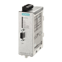
SIMATIC NET PROFIBUS, Optical Link Module
34 Operating Instructions, 07/2008, A2B00065774O, Edition V1.5
¾ Only use shielded twisted pair for the RS-485 bus cables as described in the
manual “SIMATIC NET PROFIBUS Networks”. Do not exceed the segment
lengths specified there.
¾ Connect the RS-485 bus segment via a PROFIBUS connector. If the module is at
the beginning or at the end of a bus segment, this connector must have an active
bus terminator.
¾ All PROFIBUS bus connectors of the network must be screwed securely to the RS-
485 ports.
¾ Connecting or removing the bus connector or loosely connected bus connectors or
bus wires not secure inside the connectors can lead to disruptions in the optical
and electrical network.
¾ Connect or remove the RS-485 bus connector sharply and without tilting or levering
the connector.
¾ Disconnect the RS-485 bus cable from the OLM when there is no device at the
other end or when there is no power supplied to it. Otherwise the open line acts like
an antenna and is susceptible to noise.
¾ In order to minimize disturbances, keep to the following order when connecting an
RS-485 bus cable to a PROFIBUS OLM when the network is active:
1. Plug the RS-485 bus connector onto the relevant device (e.g. the programming
device) and secure it with the screws.
2. Insert the RS-485 bus connector in the PROFIBUS OLM with a sharp movement
and without tilting the connector.
Carry out the steps in the reverse order to disconnect a device from the network.
¾ Make sure that the bus segment connected to the RS-485 port is terminated at
both ends. Only use a connecting cable that is terminated at both ends to connect
a single device.
¾ If temperatures in excess of 70 °C can occur on the cables or their insertion points
or the temperature at cable branching points can exceed 80 °c, special measures
must be taken. For ambient temperatures of 50 °C, cables with a temperature
rating for at least 80 °C should be used.
Compatibility notice:
In the OLM V3, pin 2 was additionally connected with ground and pin 1 with the shield.
This does not conform with the relevant standard EN 50170 /2/. This presents no
problem, when cables complying with the PROFIBUS standard are used. When
installing in an existing cabling system, check the pin assignment and modified it if
necessary.
Please note the following safety information:
Do not connect RS-485 bus cables to the OLM that are laid completely or partly outside
buildings. Lightning strikes in the vicinity could otherwise destroy the modules. If the bus
exits the building, use fiber-optic cables!
 Loading...