Product Characteristics
4.2 Installation
SIMATIC NET PROFIBUS, Optical Link Module
Operating Instructions, 07/2008, A2B00065774O, Edition V1.5
25
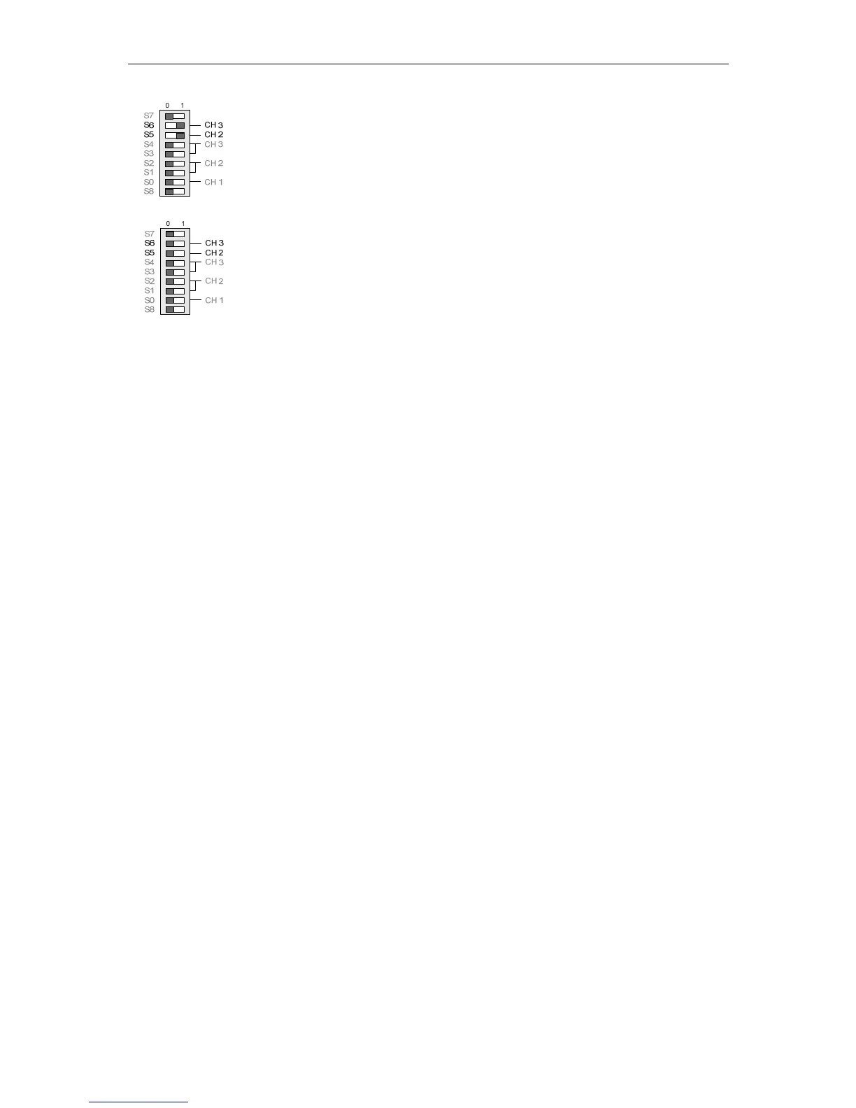
Leave S5 in position 1 (default) if the fiber-optic link on CH2 works correctly in this
position.
Leave S6 in position 1 (default) if the fiber-optic link on CH3 works correctly in this
position.
Set S5 to position 0 (reduced) if overdrive of a non-OLM device occurs on CH2
when plastic fiber-optic cables are used.
Set S6 to position 0 (reduced) if overdrive of a non OLM-device occurs on CH3
when plastic fiber-optic cables are used.
Note:
When using PCF fibers, the default transmit power must be set (S5 or S6 in
position 1).
If OLM V4-P11 / OLM V4-P12 is operated along with OBTs, IM151-1 FO, CP 5613
FO/CP 5614 FO, IM 467 FO, CP 342-5 FO or IM 153-2 FO devices using S
980/1000 plastic fiber cables, the devices must be interconnected by fiber-optic
cables with a minimum length of 30 m. As an alternative, a fixed attenuator with an
attenuation value between 5 dB and 15 dB can be used. The fixed attenuator must
be installed into the OLM receiver line. If PCF fibers S 200/230 are used, neither a
minimum line length nor an attenuator is necessary.
4.2.3.6 DIL Switches S5 / S6 in OLM V4-G11/G12/G11-1300/G12-1300
In OLM V4 devices for glass FOC, the DIL switches S5 and S6 do not have a
function (reduction of optical transmit power not possible). Nevertheless, if the OLM
V4 is used along with OLM V3-G11/G12/G11-1300 and G12-1300 devices, the DIL
switches S6 and S5 of the OLM V3 must be set to "0" in order to avoid interference
due to the internal design of the OLM V3 devices.
4.2.3.7 Mixed operation of OLM V4 with OLM V2 (SINEC L2FO)
If OLM V4 modules are used along with OLM V2 (SINEC L2FO) modules, the bus
terminating resistors for the second RS-485 port must be activated on the OLM V2
if the port is not used. This is done by setting DIL switches S3 and S4 (termination)
to ON.
 Loading...