Operation modes
5
22 | 34 A6V11571319_en--_b
It is not permitted to cross over between different loop connections. Wiring must
run from the 'Start' loop connection to the 'End' loop connection of the very same
loop.
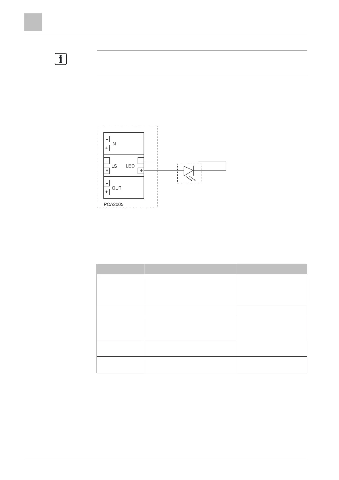
5.2.2 Connection diagram, external LED indicator
An external LED can be mounted to display the status of the loop isolator.
● The external LED replaces the internal LED as the status display.
● The external LED must be configured using the SIL switch.
Fig. 8: Connection diagram, external LED
See also
Adjustment elements [➙ 31]
5.3 Operation modes
Mode Description Pilot tone
Normal Loop isolator is in regular operation Pilot tone 20kHz
Interval adjustable in
'PACE-Design'
configuration
Alarm An alarm message is playing Pilot tone constant 21 kHz
Maintenance
Could be activated via 'PACE-
Design': Supervision, General
Flags, 'EN Maintenance' active
Pilot tone 20 kHz
Interval fixed On: 5 s, Off:
2 s
Inspection LED flashes after 90 s pilot tone
Pilot tone constant 20 kHz
< 90 s
Module fault
reset
Pilot tone at least 60 s off or pilot
tone constant for 30 s on
Pilot tone 20 kHz
 Loading...