Dyna-Flo Control Valve Services Ltd.
Phone: 780 • 469 • 4000 | Toll Free: 1 • 866 • 396 • 2356 | www.dynafl o.com
P-PS2Q0619A
9
NEW LINEAR MOUNTING INSTRUCTIONS
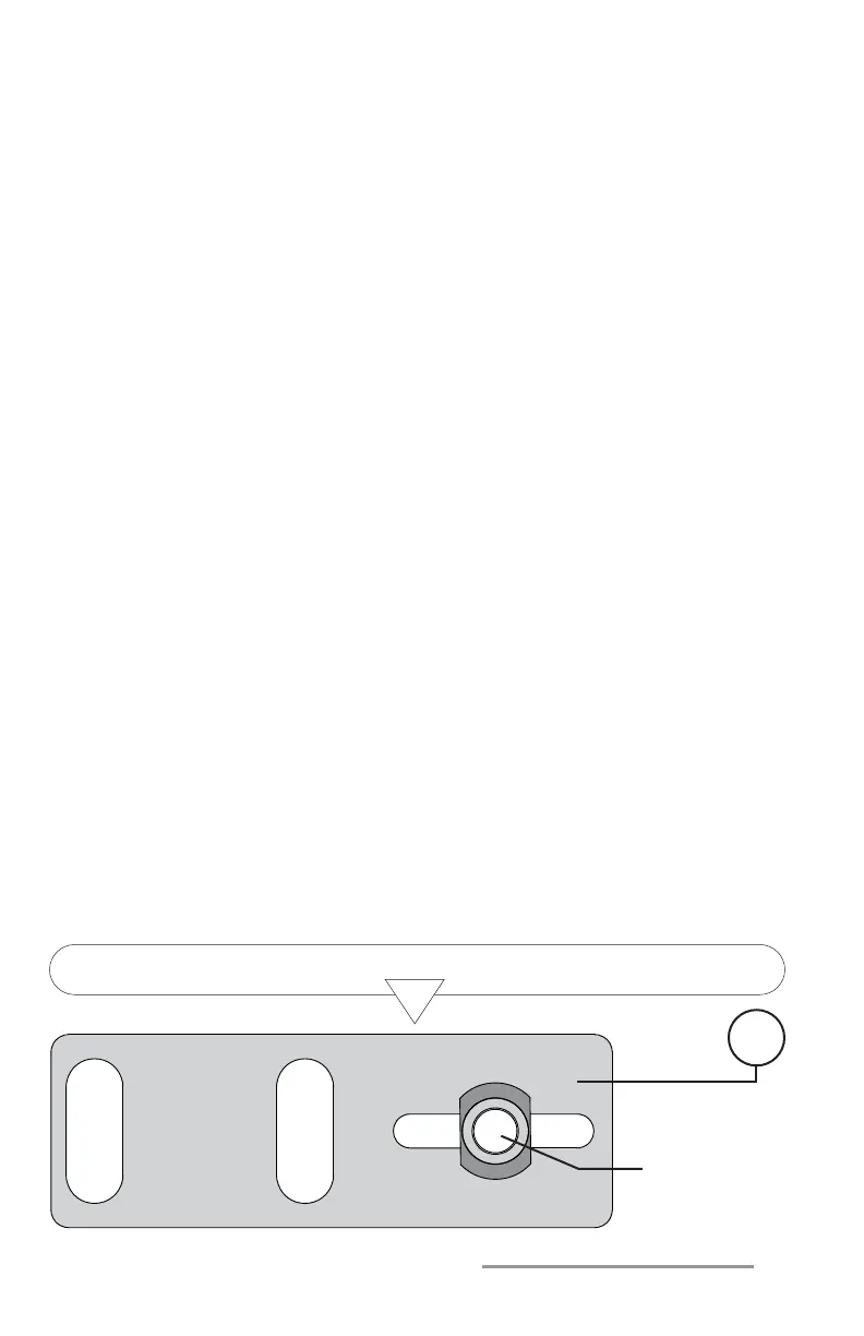
Figure 4A Sliding Pin Placement Connecting Block Bracket
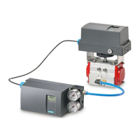
SIEMENS PS2 LINEAR MOUNTING INSTRUCTIONS (Continued):
3 Determine the required travel for your valve assembly and locate the
corresponding mounting holes on the yoke bracket (Key 8), refer to Figure
4C for example. Attach the yoke bracket/PS2 positioner assembly to the lower
mounting pad of the actuator yoke with lock washers (Key 14), cap screws
(Key 13), and spacers (Key 15) if required (refer to Table 1 to determine if
spacers are required). NOTE: Before tightening the mounting cap screws,
ensure that the sliding pin assembly is aligned in the feedback arm slot as
shown in Figure 5B.
4 Adjust the hex nut (Key 7) on the sliding pin assembly to achieve 1/16” to
1/4” compression on the spring (Key 4), refer to Figure 5B.
5 Set the actuator to 50% travel, the feedback arm (Key 11) should be
horizontal. If the feedback arm is not horizontal, adjust the connecting block
bracket (Key 1) up or down as necessary.
6 Place the actuator in the fully open or closed position. Adjust the sliding pin
assembly left or right in the pin slot of the connecting bracket (Key 1) to
achieve the correct angle of travel:
For 3/4” & 1-1/8” Travel: The feedback arm (Key 11) should be at 33
O
as
shown in Figure 6. Adjust the sliding pin assembly until the center of the
feedback arm slot aligns with the 3/16” hole of the yoke bracket (Key 8).
For 1-1/2” to 4” Travel: The feedback arm (Key 11) should be at 45
O
as
shown in Figure 6. Adjust the sliding pin assembly until the center of the
feedback arm slot aligns with the hex nuts (Key 10) in the mounting yoke
bracket (Key 8) where it connects to the PS2.
7 Follow the START-UP instructions described in this handbook or in the Chapter
on “Commissioning” of the Siemens SIPART PS2 from the Operating
Instructions (Latest Edition).
1
SLIDING
PIN
ASSEMBLY