Technical Reference Manual
Custom Sensor Support
In both P2 Mode (ALN device) and P1 Mode (FLN device), the PXC Compact supports
three custom sensor inputs for the AI points: Johnson Controls Nickel 1000, DIN
Standard Nickel 1000, and Thermistor 10K Type 3. These sensors display as an option
under the Sensor type HMI prompt when entering an AI point at the HMI.
>Sensor type : -
> 1) I ( Current )
> 2) V ( Voltage )
> 3) P ( Pneumatic )
> 4) T ( Thermistor 100K )
> 5) O ( Thermistor 10K )
> 6) S ( Thermistor 10K Type 3 )
> 7) M ( RTD 1K Platinum 375 )
> 8) R ( RTD 1K Platinum 385 )
> 9) N ( RTD 1K Nickel )
> 10) J ( RTD 1K Nickel JCI )
> 11) D ( RTD 1K Nickel DIN )
> 12) L ( L-Type )
> 13) C ( Custom )
Enter option # or <C> for Cancel> 1-
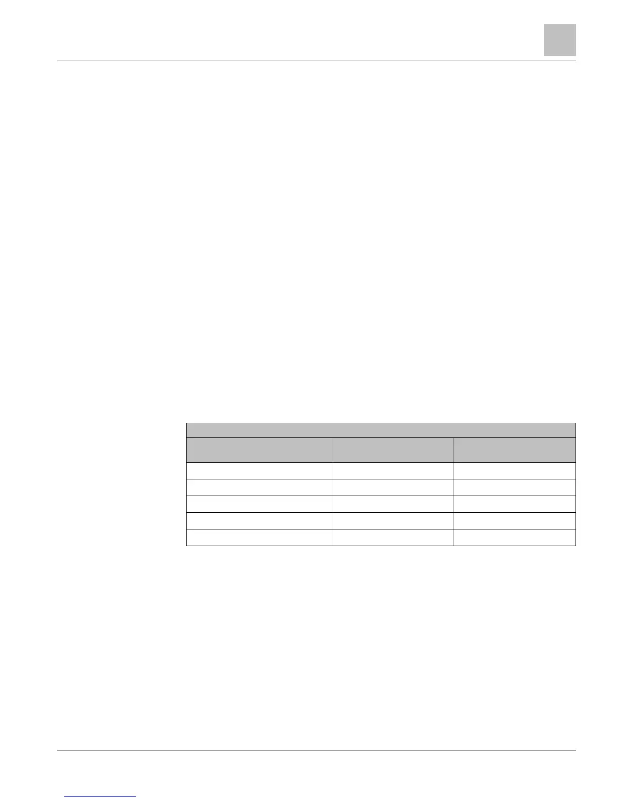
For the two RTD sensors, use the following updated
Intercept Adjustments
table to
create the value entered at the > Wire resistance adjustment : prompt.
RTD Type and temperature
coefficient
1
Intercept Formula for
Fahrenheit
2 3
Intercept Formula for Celsius
2 4
(M) RTD 1K Platinum 375 I - (R × ft)/2.117 I - (R × m)/3.8102
(R) RTD 1K Platinum 375 I - (R × ft)/2.171 I - (R × m)/3.9080
(N) RTD 1K Nickel I - (R × ft)/2.459 I - (R × m)/4.427
(J) RTD 1K Nickel JCI I - (R × ft)/2.9667 I - (R × m)5.3400
(D) RTD 1K Nickel DIN I - (R × ft)/3.0589 I - (R × m)5.5060
1)
Intercept Formula uses average temperature coefficient for the sensor connected.
2)
Resistance (
) is from the wire specification or the typical wire resistance table.
3)
is for the intercept from the field panel Slope/Intercept table and
is the wire length in feet.
4)
is for the intercept from the field panel Slope/Intercept table and
is the wire length in meters.
Memory
The APOGEE firmware (program), its point database, PPCL program, trend data, and
other information reside in the field panel memory. Memory consists of two areas:
Flash Read-Only Memory (Flash ROM) and Random Access Memory (RAM).