SD39RIO-1 INSTALLATION
January 2001
2-7
or install screw anchors. You are to supply the appropriate fastening hardware.
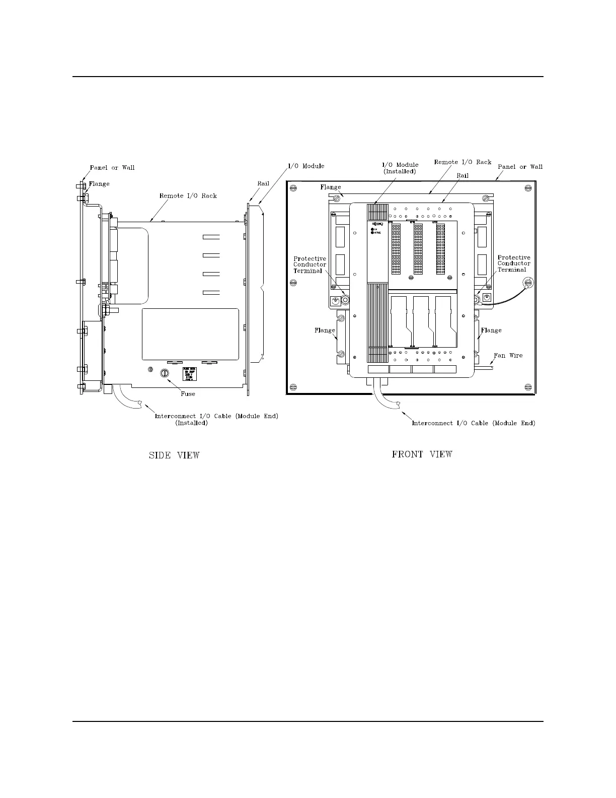
5. Position the Remote I/O Rack at its mounting position on the flat surface (wall or instrument panel) and
secure it in place with the appropriate fasteners.
Figure 2-3 Mounting a Remote I/O Rack
2.4 APACS+ Cable Latching and Strain Relief Mechanisms
APACS+ employs two cable latching mechanisms; the spring latch type and the screwlock type. The plug-in
type IOBUS connectors on the backplane of the Remote I/O Rack, and all associated cables listed in Table 5-
3, feature the screwlock type mechanism. Earlier APACS+ system devices used spring latch cable parts and
cable connection points. To accommodate system upgrade or retro-fit situations where a cable must mate
with an incompatible connector, a Cable Adapter Kit (P/N 16056-593) is available for conversion from the
spring latch type to screwlock type or vice versa.
The Remote I/O Rack features IOBUS connectors at each IOBUS connection point. As shown in Figure 2-4,
IOBUS A/B IN connection points are on the left side of the rack’s backplane and IOBUS A/B OUT
connection points are on the right side. Each IOBUS connection point has both a screw lock connector and
screw terminals connected in parallel to accommodate various IOBUS connection schemes.