SD39RIO-1 INSTALLATION
January 2001
2-9
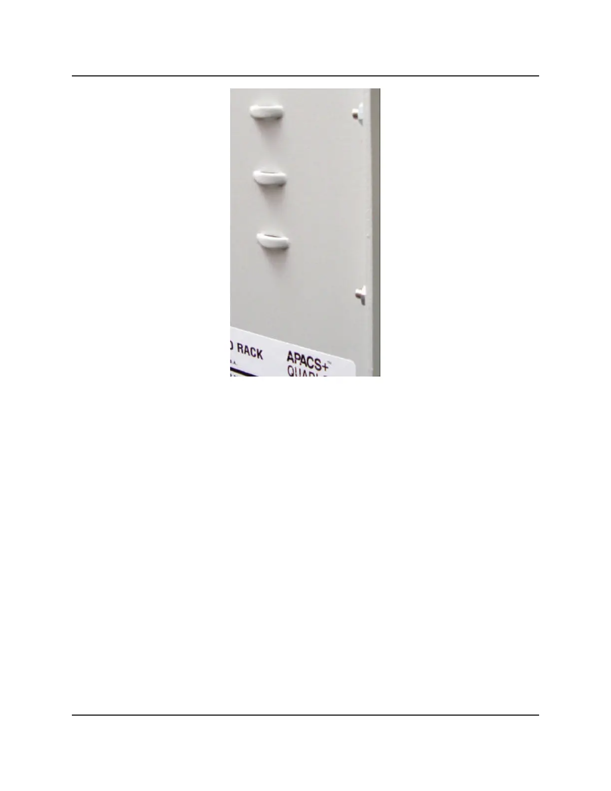
Figure 2-5 Cable Tie Points for Strain Relief
IMPORTANT
APACS+ and QUADLOG hardware is certified to meet certain safety agency
(EMC, CSA) vibration, and temperature standards. To ensure that test certifications
are not violated, note the following:
• ESD covers and dust covers on unused connectors must be attached at all times.
• Cables must be secured at all times by screwlock mechanisms.
• No unauthorized modifications are allowed to APACS+ or QUADLOG products.
2.5 IOBUS Cable and Shunt/Jumper Connections
The IOBUS is redundant (sides A and B) and can have a maximum capacity of 40 nodes defined as one
control module and up to 39 I/O modules. The actual nodal capacity depends upon the type of rack used or
the combination of racks used (see section 2.2.2).
A minimum node IOBUS consists of two modules: a control module and an I/O module; however, the control
module must reside in a SIXRAC or a MODULRAC to communicate over the MODULBUS (M-BUS). The
IOBUS capacity of a Remote I/O Rack is fixed at four modules (nodes) and cannot be configured into
separate segments; however, the Remote I/O Rack’s IOBUS can continue into other Remote I/O Racks,
SIXRACs, MODULRACs, or UNIRACs. IOBUS cables and shunts (see Figures 2-6 through 2-10) are used
to establish the physical length of an IOBUS.