85 / 94
Siemens RDF800KN.., RDF800KN/VB, RDD810KN/NF Basic documentation CE1P3174en
Smart Infrastructure 2020-02-21
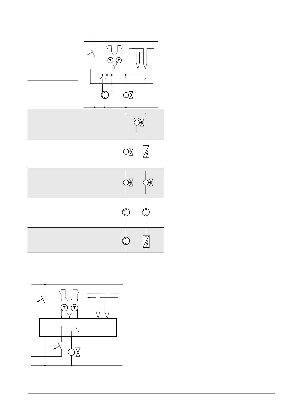
6.2 Connection diagrams
Application
RDF800KN..,
RDF800KN/VB
N1 Room thermostat RDF800KN..,
RDF800KN/VB
M1 1-speed or 3-speed fan
V1 Valve actuator, 2- or 3-position
V1, V2 Valve actuator, 2-position
E1 Electric heater
C1, C2 1-stage compressor
S1, S2 Switch (keycard, window contact,
presence detector, etc.)
B1, B2 Temperature sensor (return air
temperature, external room
temperature, changeover sensor,
etc.)
CE+ KNX data +
CE- KNX data –
2-pipe/heating or
cooling – On/Off
2-pipe/heating or
cooling – 3-position
– Y1 = open
– Y2 = close
2-pipe and electric
heater/
heating or cooling
and electric heater
4-pipe/
heating and radiator
– V1 = heating
– V2 = cooling
1-stage compressor
– C1 = heating
and/or
– C2 = cooling
1-stage compressor
and electric heater
N1 Room thermostat
V1 Valve actuator
Lx AC 24...230 V
S1, S2 Switch (keycard, window contact, presence detector,
etc.)
B1, B2 Temperature sensor (return air temperature, external
room temperature, changeover sensor, etc.)
CE+ KNX data +
CE- KNX data –
Application
L
N
10 A
L
N
Y1
Y2
AC 230 V
X1
M
X2
N1
M1
V1
5(2)A
Max.
5(2)A
Max.
B2
S2
B1
S1
Q1 Q2 Q3
I II III
CE+ CE-
KNX
V1
5(2)A
Max.
E1
5(2)A
Max.
5(2)A
Max.
V1
C1
5(2)A
Max.
V1
5(2)A
Max.
V2
5(2)A
Max.
C1
5(2)A
E1
5(2)A
C2
5(2)A
Max.
L
N
10 A
L
N
AC 230 V
X1
M
X2
N1
V1
5(2)A
Max.
B2
S2
B1
S1
Q11 Q14 Q12
CE+ CE-
KNX
Lx
10 A
 Loading...