Chapter 2
Installing the Device
RUGGEDCOM RMC20
Installation Guide
10 Setting the Operating Mode
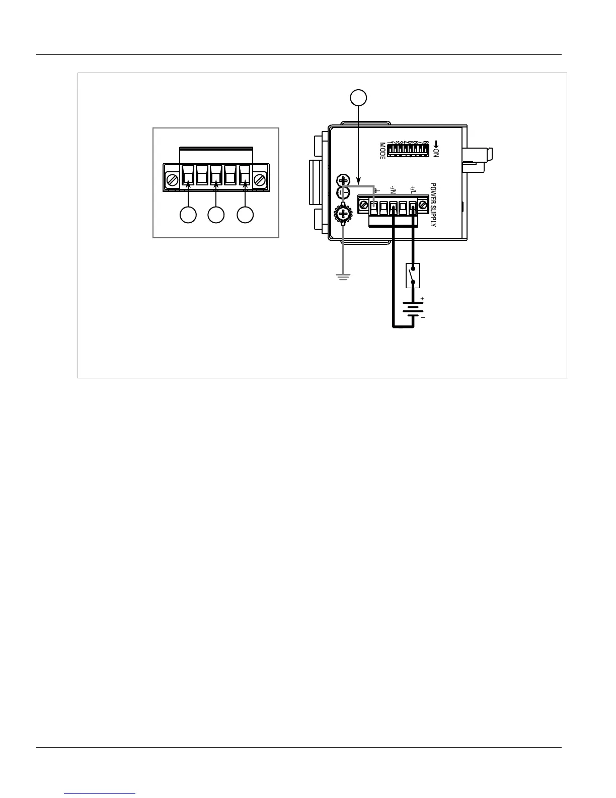
Figure5:Terminal Block Wiring
1.Positive/Live (+/L) Terminal 2.Negative/Neutral (-/N) Terminal 3.Surge Ground Terminal 4.Braided Ground Cable
2. Connect the negative wire from the power source to the negative/neutral (-/N) terminal on the terminal block.
3. Using a braided wire or other appropriate grounding wire, connect the surge ground terminal to the chassis
ground connection. The surge ground terminal is used as the ground conductor for all surge and transient
suppression circuitry internal to the unit.
4. Connect the ground terminal on the power source to the chassis ground terminal on the device.
Section2.3
Setting the Operating Mode
To accommodate a wide array of serial devices, the RUGGEDCOM RMC20 is equipped with a MODE DIP switch
located on the bottom of the device. The switch configures the RUGGEDCOM RMC20 to accommodate different
serial partners that operate at various duplex modes and speeds. Choose the appropriate operating mode
according to the serial link partner.
 Loading...