RUGGEDCOM RMC20
Installation Guide
Chapter 2
Installing the Device
Serial Standard Conversion 13
Section2.3.2
Serial Standard Conversion
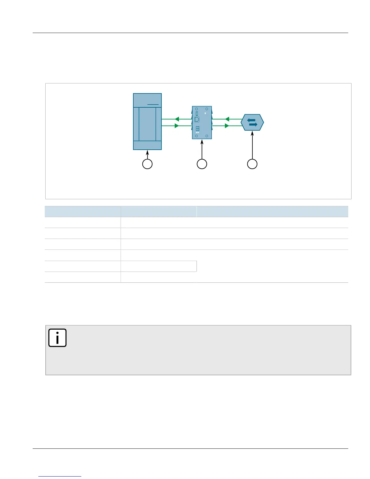
The following illustrates the connections for conversion between RS232 and RS485/422 devices.
Figure8:RS232 to RS485/422 Topology
1.RS232 Device 2. RUGGEDCOM RMC20 3.RS485 Device/Network
Position State Notes
2 ON Serial Conversion Mode
3 OFF Half Duplex
4 OFF Fiber repeat OFF
6 OFF
7 OFF
8 ON
9600 Baud
In this mode of operation, RS232 voltage levels are converted to the appropriate RS485 or RS422 signalling levels
depending on the DIP switch configuration. In this mode of operation position 2 of the DIP switches must be in
the ON position. The topology depicted in Figure 8 illustrates an RS232 device, connected to an RS485 device or
network. Since RS485 requires automatic turn-around, position 3 must be set to the OFF state, and position 6 – 8
of the DIP switches must reflect the proper operating baud rate.
NOTE
In this mode of operation, no isolation is provided between RS232 device and the RS485/422 network
– both devices share the same common terminal. It should be noted that the common terminal on
RS232 devices are connected to ground. In some instances (i.e. when connecting to large RS485
networks), it may be preferential for the user to leave the RS485/RS422 shield terminal unconnected to
the RUGGEDCOM RMC20 in this mode.
Section2.3.3
Serial-to-Fiber Conversion: Loop Topology
The following illustrates the optical loop topology that utilizes the RUGGEDCOM RMC20 repeat mode function.
 Loading...