Chapter 2
Installing the Device
RUGGEDCOM RMC20
Installation Guide
14 Serial-to-Fiber Conversion: Loop Topology
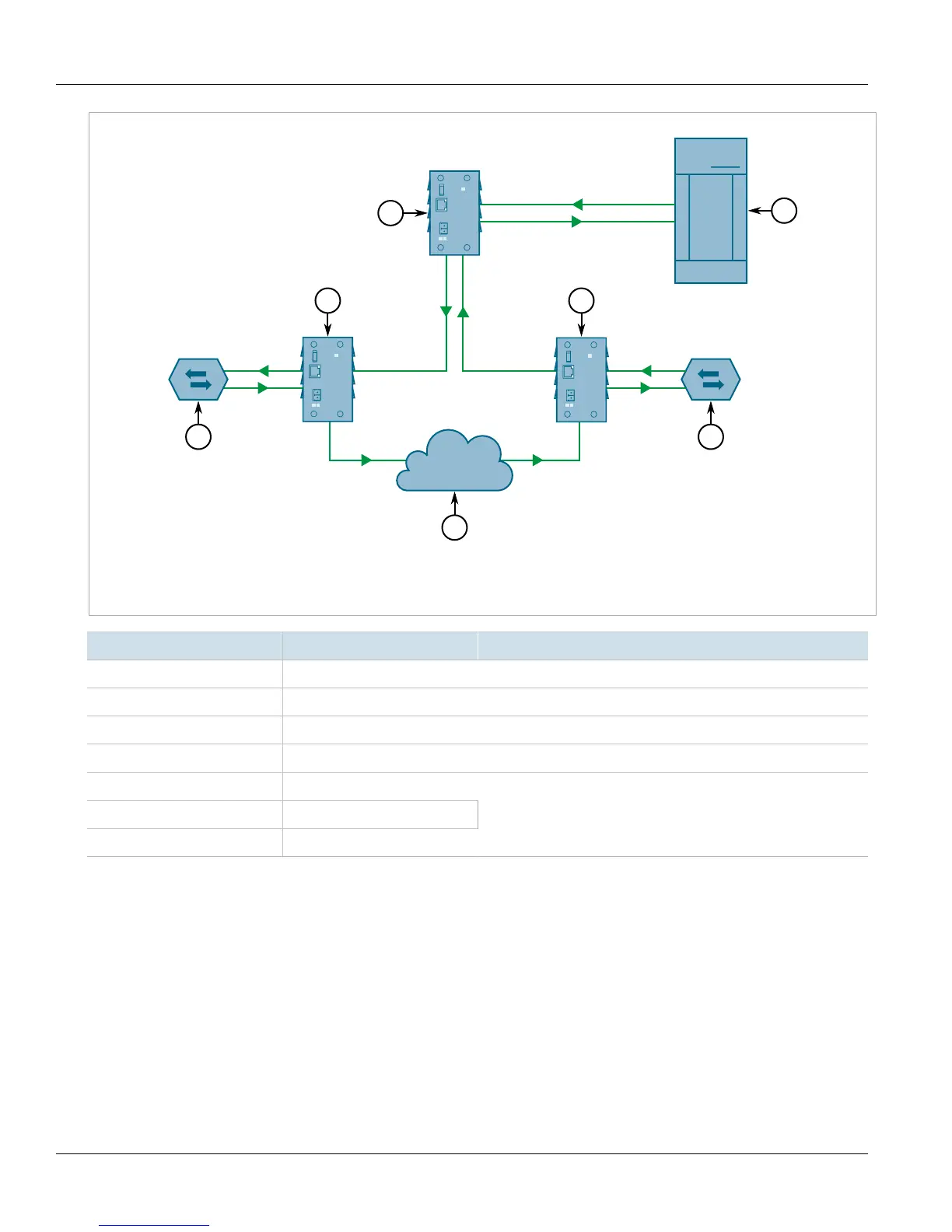
Figure9:Serial-to-Fiber Conversion in Example Optical Loop Topology
1.RS485 Slave (Repeat = ON) 2. RUGGEDCOM RMC20 3.Multiple RUGGEDCOM RMC20 Devices 4.RS485 Master (Repeat = OFF)
Position State Notes
1 OFF RS485/422 <-> Fiber
2 OFF Serial-to-Fiber Mode
3 OFF Half Duplex
4 OFF Fiber repeat: Refer to Figure 9
6 OFF
7 OFF
8 ON
9600 Baud
The repeat function will optically re-transmit any data received on the optical receiver, in addition to any
connected serial devices. As a result, any data transmitted from the master, will be re-transmitted optically to all
the slaves. This mode of operation requires that the master device tolerate receiving echoes of transmitted data
since any transmissions will be received once again via the optical ring.
This topology can be used for RS232, RS485 or RS422 multi-drop networks. In all cases, all slaves have the repeat
function (DIP position 4) ON, while the master is configured with the repeat function OFF. This topology can allow
for the mixture of RS232, RS485 and RS422 devices, operating on the same baud rate, on a single optical serial
network because the RUGGEDCOM RMC20 utilizes a common optical signalling protocol for all serial standards.
 Loading...