Introduction
1.3Required Tools and Materials
8
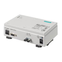
Chassis Ground Terminal
Figure1.1 RUGGEDCOM RMC20
POWER LED Illuminates when power is being supplied to the device.
State Description
Green Power is on
Off Power is off
TX/RX LEDs Indicate the connection status of the serial terminal.
LED State Description
TX Yellow
(Blinking)
Transmitting serial data
RX Yellow
(Blinking)
Receiving serial data
Serial Terminal The RS232/RS422/RS485 serial terminal serves a dual purpose:
• The RS232 terminals allow for a direct interface with the device
and access to initial management functions.
• The RS422/RS485 terminals allow for half or full duplex serial
connections respectively. For more information, refer to
"Communication Ports (Page 17)".
Power Supply Terminal A pluggable terminal. For more information, refer to:
• "Connecting Power (Page 14)"
• "Power Supply Specifications (Page 23)"
MODE Switch Sets the operating mode for the device. For more information, refer
to "Setting the Operating Mode (Page 9)".
Communication Ports Receive and transmit data. For more information about the
various ports available for the RUGGEDCOM RMC20, refer to
"Communication Ports (Page 17)".
1.3 Required Tools and Materials
The following tools and materials are required to install the RUGGEDCOM RMC20:
Tools/Materials Purpose
AC or DC power cord (16 AWG) For connecting power to the device.
CAT-5 Ethernet cables For connecting the device to the network.
Flathead screwdriver For mounting the device to a DIN rail.
Phillips screwdriver For mounting the device to a panel.
4 x #8-32 screws For mounting the device to a panel.
1.4 Decommissioning and Disposal
Proper decommissioning and disposal of this device is important to prevent malicious
users from obtaining proprietary information and to protect the environment.
RUGGEDCOM RMC20
Installation Manual, 04/2021, C79000-G8976-1007-10
3

 Loading...