Chapter 2
Installing the Device
RUGGEDCOM RS8000T
Installation Guide
14 Connecting DC Power
CAUTION!
Electrical hazard – risk of damage to equipment. Before testing the dielectric strength (HIPOT) in the
field, remove the braided ground cable connected to the surge ground terminal and chassis ground.
This cable connects transient suppression circuitry to chassis ground and must be removed in order to
avoid damage to transient suppression circuitry during testing.
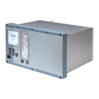
1. Connect the positive wire from the power source to the positive/hot (+/L) terminal on the terminal block.
Figure8:Terminal Block Wiring
1.Positive/Hot (+/L) Terminal 2.Negative/Neutral (-/N) Terminal 3.Surge Ground Terminal 4.Braided Ground Cable
2. Connect the negative wire from the power source to the negative/neutral (-/N) on the terminal block.
3. Using a braided wire or other appropriate grounding wire, connect the surge ground terminal to the chassis
ground connection. The surge ground terminal is used as the ground conductor for all surge and transient
suppression circuitry internal to the unit.
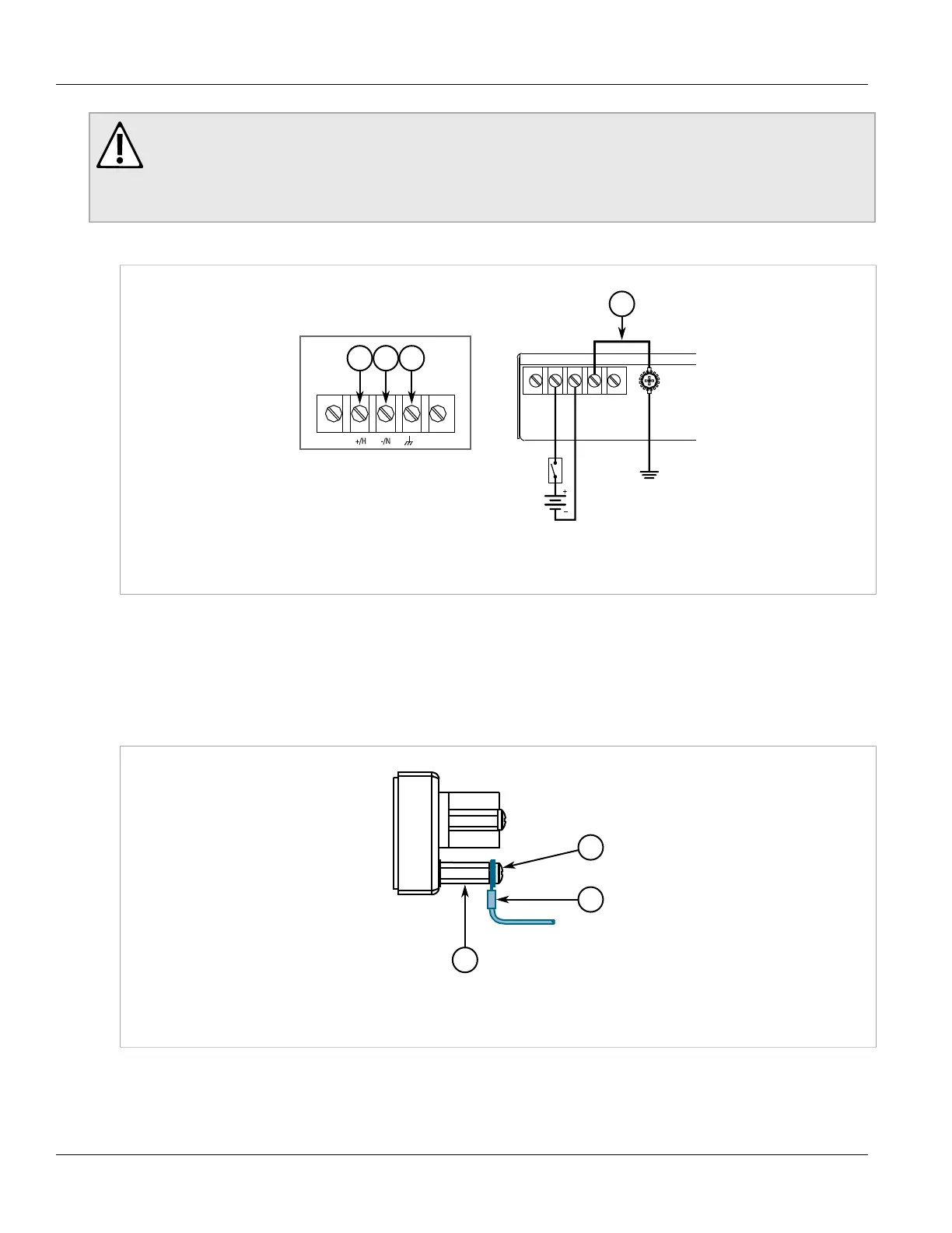
4. Using a #6 ring lug and #6-32 screw, secure the ground terminal on the power source to the chassis ground
terminal on the device. Make sure the lug is tightened to 1.7 N·m (15 lbf·in).
Figure9:Chassis Ground Connection
1.Stainless Steel Stud 2.#6-32 Screw 3.#6 Ring Lug
 Loading...