RUGGEDCOM RSG909R
Installation Guide
Chapter 1
Introduction
Required Tools and Materials 3
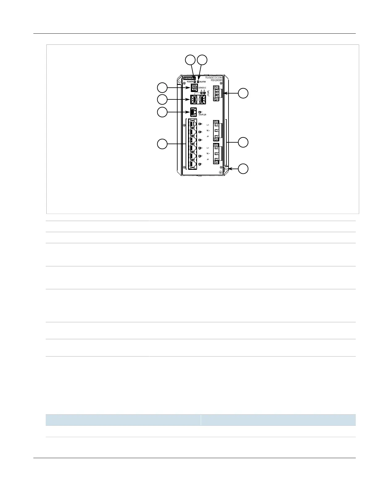
Figure1:RUGGEDCOM RSG909R
1.POWER LED 2.ALARM LED 3.USB Console Port 4.RNA Port (Port A/B) 5.Port 7 6.Copper Ethernet Ports (Ports 1 to 6) 7.Failsafe
Alarm Relay 8.Power Supply Terminal Blocks 9.Chassis Ground Screw
POWER LED Illuminates green when power is supplied to the device.
ALARM LED Illuminates red when an alarm condition exists.
Console Port The USB Type-B console port is for interfacing directly with the device and accessing initial
management functions. For information about connecting to the device via the serial
console port, refer to Section3.1, “Connecting to the Device”.
Communication Ports Communication ports in general receive and transmit data, as well as provide access to the
RUGGEDCOM ROS Web interface. For more information about the various ports available,
refer to Chapter4, Communication Ports.
Failsafe Alarm Relay Latches to default state when a power disruption or other alarm condition occurs. For more
information, refer to:
• Section2.5, “Connecting the Failsafe Alarm Relay”
• Section5.2, “Failsafe Alarm Relay Specifications”
Power Supply Terminal Blocks Pluggable terminal blocks for connecting one or more power sources. For more information,
refer to Section2.6, “Connecting Power” and Section5.1, “Power Supply Specifications”.
Chassis Ground Terminal Protects the device from power surges and accumulated static electricity. For information
about grounding the device, refer to Section2.6, “Connecting Power”.
Section1.3
Required Tools and Materials
The following tools and materials are required to install the RUGGEDCOM RSG909R:
Tools/Materials Purpose
AC power cord (16 AWG) For connecting power to the device.

 Loading...