Chapter 2
Installing the Device
RUGGEDCOM RX5000
Installation Guide
12 Connecting the Failsafe Alarm Relay
Figure6:Chassis Ground Connection
1.#8-32 Screw 2.#8 Ring Lug
Section2.7
Connecting the Failsafe Alarm Relay
The failsafe relay on the Control Module (CM) can be configured to latch based on alarm conditions. The NO
(Normally Open) contact is closed when the unit is powered and there are no active alarms. If the device is not
powered or if an active alarm is configured, the relay opens the NO contact and closes the NC (Normally Closed)
contact.
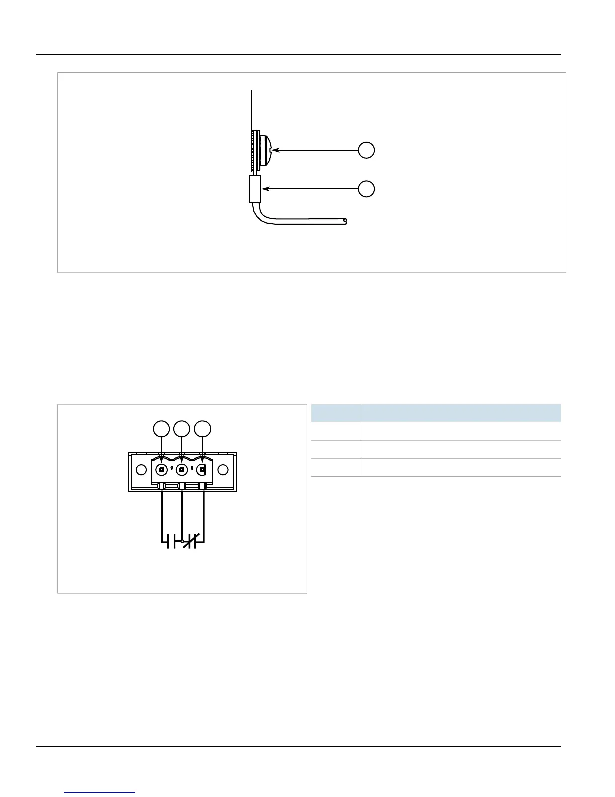
Figure7:Failsafe Alarm Relay Wiring
1.Normally Open 2.Common (Ground) 3.Normally Closed
Pin Function
NC Normally Closed
Common Ground
NO Normally Open
Section2.8
Connecting Power
The RUGGEDCOM RX5000 supports dual redundant AC and/or DC power modules that can be installed in any
combination.
The RUGGEDCOM RX5000 is equipped with a screw-type terminal block, which provides power to both power
modules. The terminal block is installed using Philips screws and compression plates, allowing either bare wire