13/69
Siemens Building Technologies Electronic Air / Fuel Ratio Control System CC1P7873.1en
HVAC Products 5 Description of functions 15.10.2002
5 Description of functions
5.1 Burner startup
The startup and shutdown sequence is determined by the burner control.
The RVW26… identifies this control sequence from the burner control's output signals.
Conversely, the RVW26… indicates to the burner control when certain actuator posi-
tions are reached (Quit).
Burner startup and shutdown take place in phases (0...7 and 8...0) that appear on the
display of the RVW26…
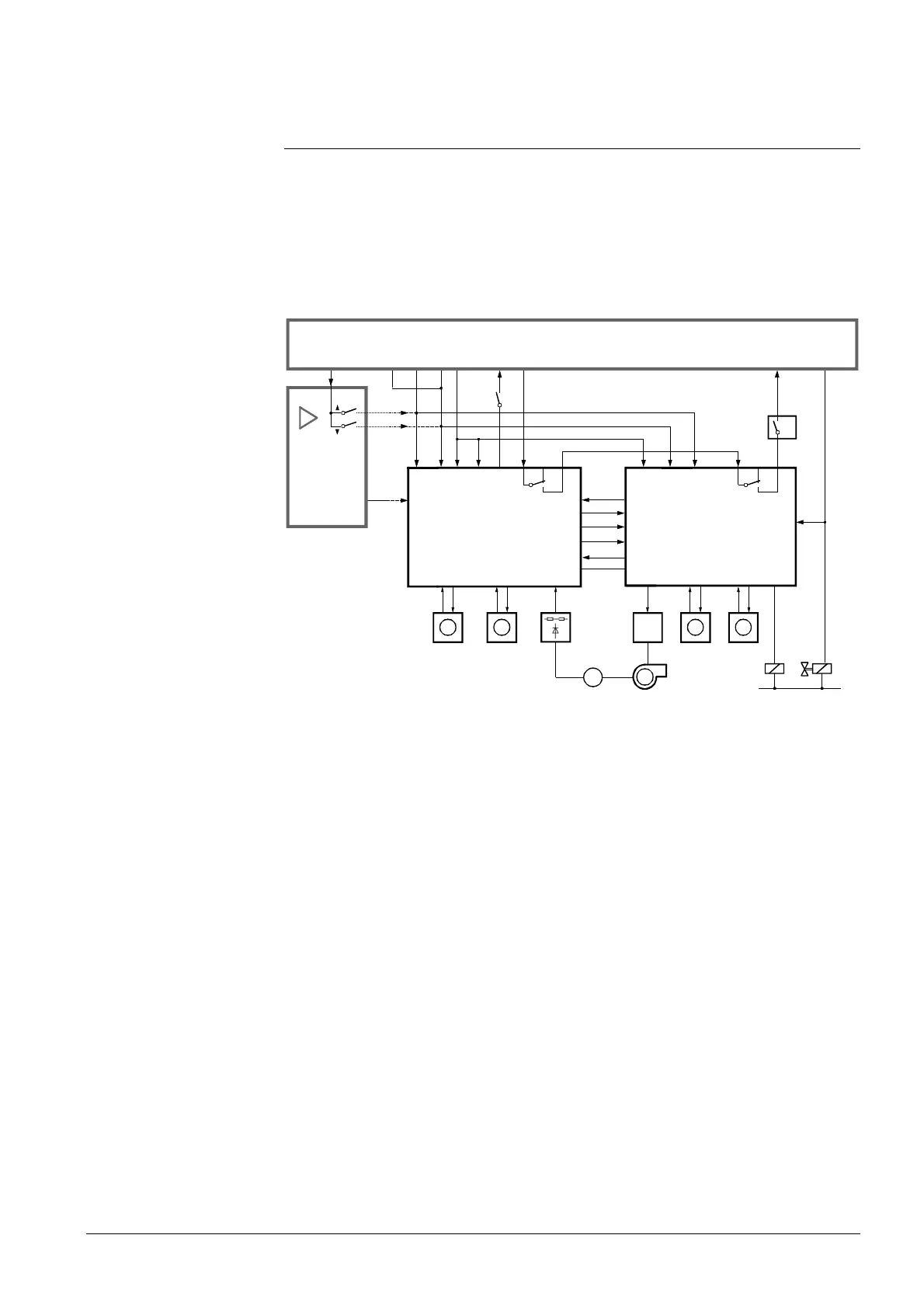
RVW25
FA
R
Q4 H Q5
FU
Q2
Y10
M
Q3
Y10
Y8
M
Q1
TG
BV1
RVW26
U1
LKZ GLKALKM
Y20
Q3
LR
M
78731a01/0601
Q1
K1
Quit
(4)
Q3A
U1X1
X3
U3
Q4 H Q5Y20
G
N
AUX
AUX1 AUX2
FUEL
(5)(20)
LR
M
BVK1
X3
Q2
(8)
(18)(7)(11)(9)(10)
TxD
RxD
TxD
RxD
GND
GND
Fig. 8 The numbers in parentheses give the terminal markings of the LAL2...,
LFL..., LGK... and LOK... (--- = analog or 3-position control signal)
The burner control’s start control loop includes control contact «R» (e.g. RWF40...) and
readiness contact «Q4...Q5».
The RVW26... detects burner startup from the signal received at input «Q3», which is
connected to the burner control’s fan output.
For safety reasons, fuel valve «BV» may not be connected in parallel to the
RVW25... and RVW26..., but only to the RVW26...
The «Q2» signal for the RVW25... is generated by output «Y8» of the RVW26...
The tables on the following pages show the startup and shutdown sequences.
 Loading...


