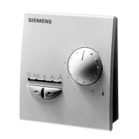
Do you have a question about the Siemens RVW26.000B27 and is the answer not in the manual?
To avoid injury to persons, damage to property or the environment, warning notes must be observed.
Ensure that relevant national safety regulations are complied with.
Installation work and settings must be carried out by qualified staff.
Commissioning work must be carried out by qualified staff.
Conformity to EEC directives.
Maintenance work must be carried out by qualified staff.
Unit may not be disposed of with household waste.
List of abbreviations and designations used in the document.
Electronic units RVW25/RVW26 designed for air/fuel ratio control.
RVW26 controls fan speed, auxiliary actuators for functions.
Lists RVW20, RVW25, RVW26 units, housings, terminals, etc.
Startup sequence determined by burner control, identified by RVW26.
Detailed sequence of burner startup steps and signals.
Set load signal from RVW25 influences fan speed via RVW26.
Programming load/position curves for each actuator and fuel type.
Readiness contact Q4-Q5 indicates operational readiness or fault.
Sequence of burner shutdown initiated by burner control.
Internal tests, display, LED status during power ON and reset.
Using terminals F1/F2 to select fuel type and activate parameters.
Controlling one or two auxiliary actuators.
Offsetting mechanical play in actuators to maintain accuracy.
Using input X2 to optimize combustion via O2 trim control.
Analog signal output corresponding to burner output at U1.
RVW26 demands defined sequence matched to burner controls.
Program sequence divided into phases for startup, operation, shutdown.
Graphical representation of burner startup, operation, and shutdown phases.
Shows connections between RVW26, RVW25, FU, and actuators.
Detailed diagram of RVW26 internal and external connections.
Lists terminal assignments for mains voltage and extra low-voltage connections.
Details voltage and function for each terminal.
Explains meanings of display codes and LED indicators.
Used for parameter setting, connected to RVW26 socket.
Stores settings, allows transfer and duplication of parameters.
Steps to transfer settings to a new unit using the data storage module.
Actions triggered by faults, burner shutdown, error codes.
Fault indication in programming mode, parameter setting unaffected.
Procedure for resetting faults via power off or command.
Distinction between external and internal faults, lockout initiation.
Table listing error codes, causes, and troubleshooting steps.
Changing parameters using handheld terminal AZW20.20.
Overview of 9 programming levels and their functions.
Explains display elements: parameter name, value, status, phase.
Setting burner output and actuator positions in normal operation.
Procedure for measuring end switches and setting interval t4.
Setting breakpoints, Disturb, Aux2Dis, and Hyster parameters.
Programming load/position curves for actuators.
Setting ignition load and actuator positions for burner startup.
Loading/storing parameters using RZD20, clearing faults.
Displaying fault codes and brief descriptions.
Wiring diagram for a modulating burner with RVW26.
Wiring diagram for a burner with O2 trim control.
Mechanical connections must be rigid, no play.
Cable requirements, mounting, actuator running times.
Stringent requirements for actuators and feedback potentiometers.
Importance of accurate fan speed control.
Procedures for checking and adjusting actuators and potentiometers.
Guidance on setting curvepoints related to burner output.
Defines limits for curvepoints and load.
Template for recording plant settings and parameters.
Table for recording curvepoints for Fuel 1.
Table for recording curvepoints for Fuel 2.
Operating voltage, frequency, power consumption, housing protection.
Transport and operation conditions for the unit.
| Product name | Siemens RVW26.000B27 |
|---|---|
| Category | Control Systems |
| Type | Relay |
| Contact Configuration | DPDT |
| Mounting Type | DIN Rail |
| Terminal Type | Screw Terminal |
| Operating Temperature | -25°C to +55°C |


 Loading...