51/69
Siemens Building Technologies Electronic Air / Fuel Ratio Control System CC1P7873.1en
HVAC Products 16 Applications 15.10.2002
16 Applications
16.1 Basic diagram of a plant with a modulating
burner (one type of fuel)
(Using the LAL..., LFL1..., LGK16... or LOK16... as a burner control and the
RWF40... as a load controller)
20
Q
RWF40
LAL2.../LFL1.../
LGK16.../LOK16...
13 5 Q13
Y1Y211109
Q141412
7
RVW25.000B27
Q5 Q1
Y20
Y10
L
Q3A Q2NH
AL1
L
N
W
EK
B1 M
X1 M
RVW26.000B27
Q5
Q1
Y20 Y10
L
Q3 U10 B4 M Y5 Y6U10 B2 M Y3 Y4Q2 NH
F1Q4
1K9
Y8
AL2
X3 MX3 M
Q3B18
BV
DC-Power
In 0...10 V
M
FU
M
78731f04/0801
U1U3
1K9
1K8
AUX2AUX1
1 2
SA5 SA7
1 2
MM
Q4F184
AGK34
TG
Y7
1K8
LP
P
Start / Stop
TxD RxD GND TxDRxD GND
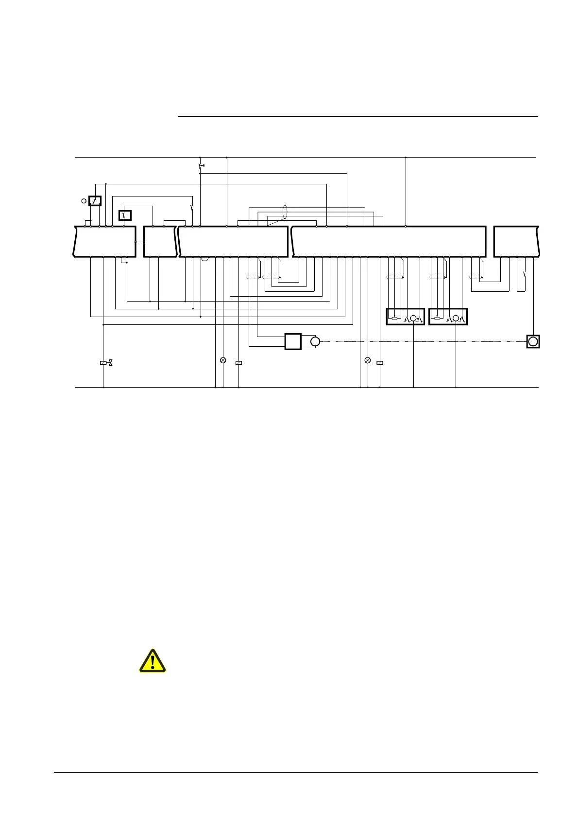
Fig. 26 Basic diagram with a modulating burner
AL Indication of nonreadiness LP Air pressure switch
BV Fuel valve M Fan motor
EK Lockout reset button SA... Actuator of … damper
FU Variable speed drive TG Tacho-generator
W Limit thermostat or pressure switch
The following contacts are included in the burner control’s start control loop (terminals
4..5):
· Readiness contact «Q4...Q5» of the RVW25... and RVW26…
· The burner’s on / off contact «Q13...Q14» of the load controller
· Limit thermostat «W» or gas pressure switch
In the event of lockout, the RVW25... and the RVW26… can be reset by pressing lock-
out reset button «EK» in the supply line. Fuel selector «F1» is connected to the line.
Terminal «F2» is not used so that the curves and parametes for fuel 1 are permanently
selected. The variable speed drive acts on the fan speed, «SA2» on the fuel valve.
«SA4», «SA5» and «SA7» are optional auxiliary actuators that can be installed if re-
quired. Signal lamp «AL» can be used for indicating faults of the RVW25... and
RVW26... With power ON of the RVW25... and RVW26... (during the self-test) the lamp
lights up for a short moment.
When sensing terminal «H» with a programmable logic controller, it must be taken into
account that with power ON or after a reset of the RVW25… and RVW26…, nonreadi-
ness or a fault of the RVW25... and RVW26… will be signaled for about 2 seconds.
Legend
 Loading...


