28/69
Siemens Building Technologies Electronic Air / Fuel Ratio Control System CC1P7873.1en
HVAC Products 6 Sequence of functions 15.10.2002
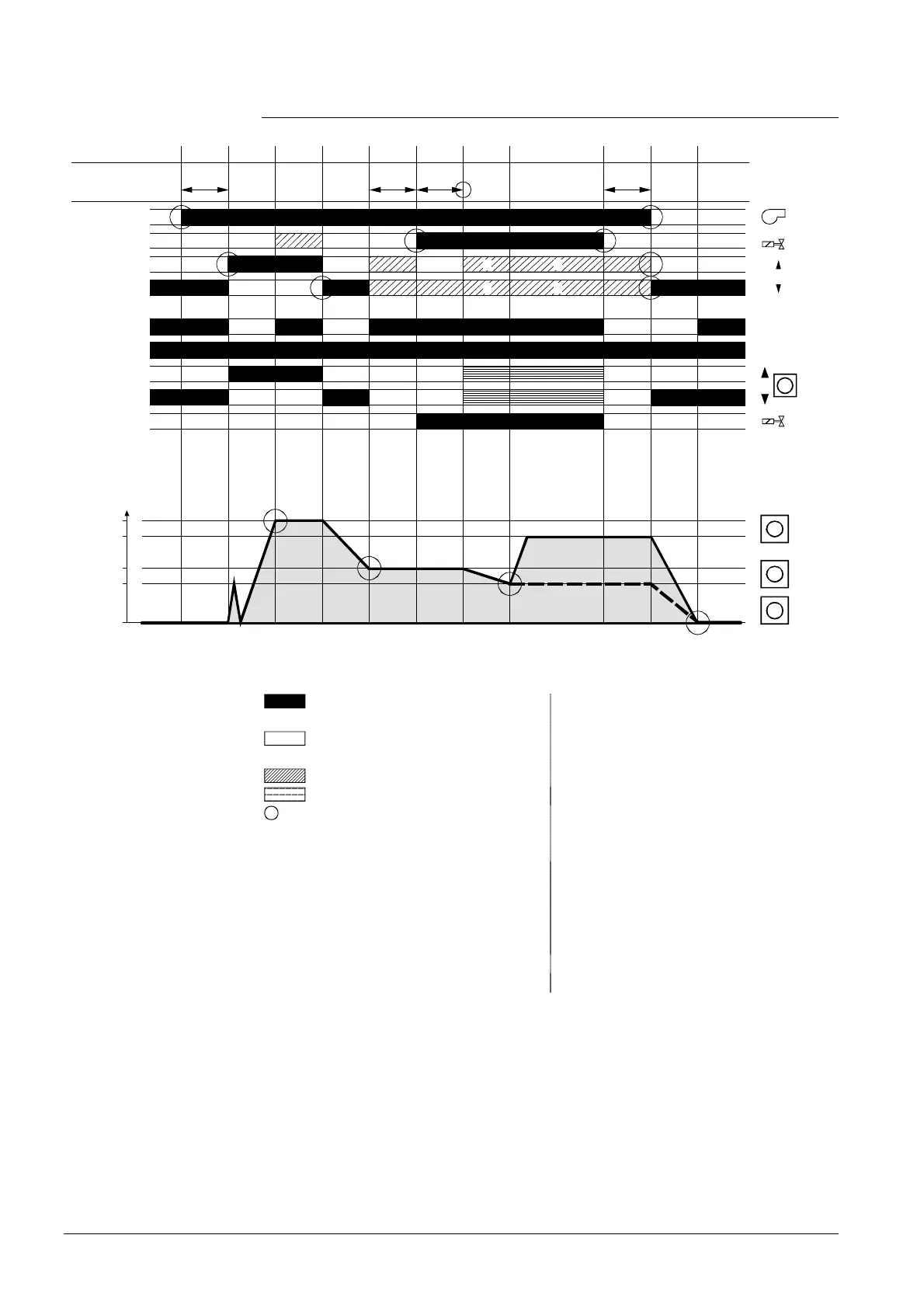
6.3 Sequence diagram
STOP
BETRIEB
SERVICE
OPERATION
1)
0 0Phase 1234567 89R
2)
2)
lim1 lim5
t4
lim8
STOP
1)
Position
Quit
Ready
R
R
AUX1,
AUX2
M
G
M
M
M
SA5
AUX1(1)
SA7
AUX2
SA6
AUX1(2)
A
Z
MaxLoad
IgnPos
MinLoad
78731d04/1002
Q3
Q2
Y10
Y20
Q1
Q4-Q5
Y3,Y5
Y8
Y4,Y6
Fig. 15 Sequence diagram
Signal must be present or output is
under voltage
1) Signals at «Y10» or «Y20» only act on
output «X1»
Signal must not be present or output
is not under voltage
2) RVW26...follows the signal at «U1» for
controlled operation
Signal can be present
Output controlled t4 Interval
Condition for transition to the next
phase
lim Duration of phase is limited.
If there is no change of phase when
the preset time is reached, lockout
will be initiated
lim1 = 30 s
lim5 = 150 s
lim8 = 30 s
Legend
 Loading...


