52/69
Siemens Building Technologies Electronic Air / Fuel Ratio Control System CC1P7873.1en
HVAC Products 16 Applications 15.10.2002
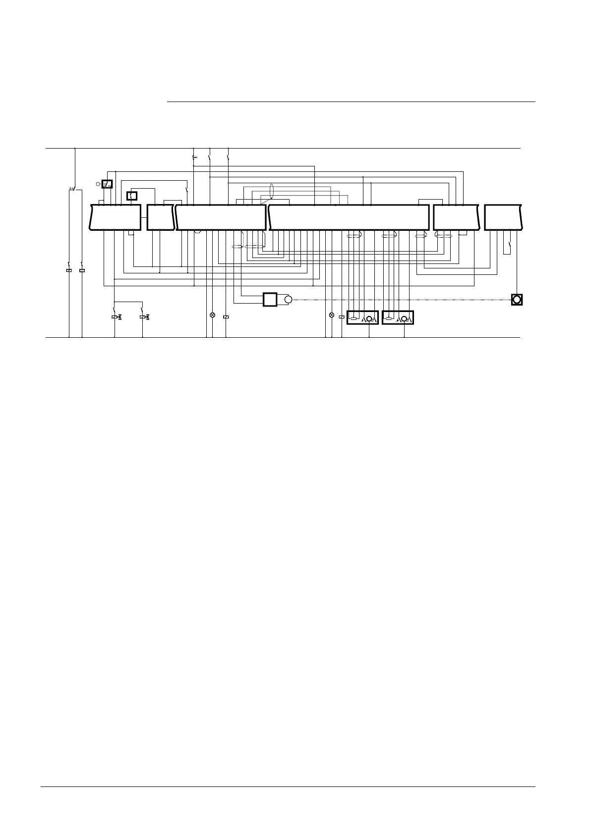
16.2 Basic diagram of a plant with a modulating
burner (one type of fuel)
(Using the LAL..., LFL1..., LGK16... or LOK16... as a burner control and the
RWF40... as a load controller with O
2 trim control)
20
Q
RWF40
LAL2.../LFL1.../
LGK16.../LOK16...
13 5 Q13
Y1Y211109
Q1414 4 812
7
RVW25
Q5 Q1
Y20
Y10
L
Q3A Q2NH
AL1
L
N
W
B1 M
X1 M
RVW26
Q5
Q1
Y20
Y10
L
Q3 U10 B4 M Y5 Y6
AUX2
U10 B2 M Y3 Y4
AUX1
1 2
SA5 SA7
Q2 NH
1 2
M
F1
1K9
Y8
M
AL2
78731f05/0801
X3 M
FU
1K8
M
X3 U1M U3
Q3B
1K4
S1
F1
F2
1K21K4
F1 F2 F2
Q7
X2GND
RPO25
F1F2
Q3Q2BQ2A
Q6
X2
X2
U1
DC-Power
Start / Stop
M
In 0...10 V
1K9
EK
1K2
1K4
1K4
Q4 Q4
AGK34
TG
Y7
1K8
P
LP
1K2
BV-F2
18
1K2
BV-F1
TXD
RXD
GND
TXDRXD
GND
Fig. 27 Basic diagram with O2 trim control
The following contacts are included in the burner control’s start control loop:
The on / off contact of the load controller (Q13...Q14), the readiness contact of the
RVW25... and RVW26… (Q4...Q5), the readiness contact of the RPO25... (Q6...Q7),
and the limit thermostat.
 Loading...


