62/69
Siemens Building Technologies Electronic Air / Fuel Ratio Control System CC1P7873.1en
HVAC Products 18 Notes on the commissioning of a burner 15.10.2002
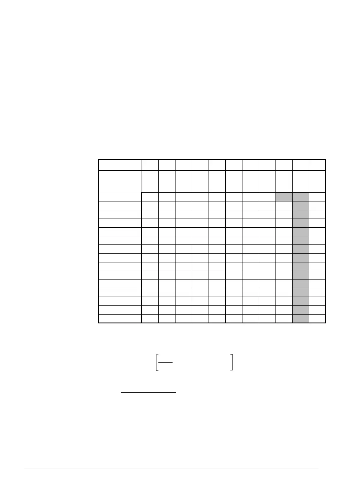
B. Curve adjustment by O2 value with the help of an auxiliary table (e.g. for 17
curvepoints, see below)
(less accurate, but quicker)
Procedure (e.g. highlighted table column)
1. Determine the amount of fuel at maximum burner output and set it. Set the fan
speed to the required O
2 setpoint (e.g. 2.20 %).
2. Set the RVW25... and the RVW26… to the next lower loadpoint (93.7 %) while
maintaining the positions for fuel and air. Here, warning «-58 / Monoton fail») will
be delivered. Ignore this message when making the next settings.
3. Reduce the amount of fuel until the O
2 value (3.37 %) listed in the table for this
load point (93.7 %) is reached.
4. Reduce the air volume until the demanded O
2 setpoint is reached. This can be ei-
ther the O
2 value of the table column used until now (2.2 %) or the value of another
column (e.g. 2.40 %). Warning «-58») must now disappear within 20 to 30 sec-
onds.
5. Repeat steps 2 through 4 until the minimum burner output is reached.
6. Interpolate the curvepoints below the low-fire position values (e.g. 0 %).
O2 setpoint [%]
4.00 3.80 3.60 3.40 3.20 3.00 2.80 2.60 2.40 2.20 2.00
Number (l)
Output (P) [%]
1.24 1.22 1.21 1.19 1.18 1.17 1.15 1.14 1.13 1.12 1.11
100 4.00 3.80 3.60 3.40 3.20 3.00 2.80 2.60 2.40 2.20 2.00
93.75 5.06 4.87 4.68 4.49 4.31 4.12 3.93 3.74 3.56 3.37 3.18
87.50 5.13 4.94 4.75 4.57 4.38 4.19 4.01 3.82 3.63 3.46 3.26
81.25 5.21 5.02 4.84 4.65 4.46 4.28 4.09 3.91 3.72 3.54 3.35
75.00 5.30 5.12 4.93 4.75 4.56 4.38 4.19 4.01 3.82 3.64 3.45
68.75 5.41 5.23 5.04 4.86 4.68 4.49 4.31 4.13 3.94 3.76 3.58
62.50 5.54 5.35 5.17 4.99 4.81 4.63 4.45 4.26 4.08 3.90 3.72
56.25 5.69 5.51 5.33 5.15 4.97 4.79 4.61 4.43 4.25 4.07 3.89
50.00 5.88 5.70 5.52 5.34 5.17 4.99 4.81 4.63 4.46 4.28 4.10
43.75 6.11 5.94 5.76 5.59 5.41 5.24 5.06 4.89 4.71 4.54 4.36
37.50 6.41 6.24 6.07 5.90 5.73 5.56 5.39 5.21 5.04 4.87 4.70
31.25 6.82 6.65 6.48 6.32 6.15 5.98 5.82 5.65 5.48 5.32 5.15
25.00 7.38 7.22 7.06 6.90 6.74 6.58 6.42 6.26 6.10 5.94 5.78
18.75 8.23 8.08 7.93 7.78 7.63 7.48 7.33 7.18 7.03 6.87 6.73
12.50 9.63 9.50 9.37 9.23 9.10 8.97 8.83 8.70 8.57 8.43 8.30
Procedure:
1. Consider the admissible range of curvepoints
2. Calculate the O
2 table values:
O2new = 20.9 % - x (20.9 % - O2 setpoint)
Pnew
Pold
3. Calculate the air number (l):
=
20.9 %
(20.9 % - O2 setpoint)
l
O2 setpoint O2 table value of the load (P = 100 %)
O
2new O2 value after fuel reduction
Pnew Required load value after fuel reduction
Pold Current load value before fuel reduction
Creating the
auxiliary table
Legend
 Loading...


