6 Operation
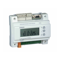
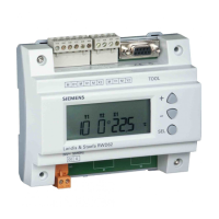
6.1 Meaning of display and buttons
Burner release
Operating mode 2-stage
Actual value display (red)
and parameter value
USB-LED
Setpoint display (green)
and parameter symbol
Enter button
Increase value
Controlling
element CLOSE
Controlling
element OPEN
ESC button
Decrease value
Enter
ESC
7866z03e/0212
RWF50.x
Figure 16: Meaning of display and buttons
The two 7-segment displays (red and green) show hyphens and all LEDs light up for
about 5 seconds.
The upper display (red) shows the actual value.
The lower display (green) shows the setpoint.
Reference!
See chapter 8.6 Display diSP.
When entering parameters, the parameter symbol at the bottom (green) and the set
value at the top (red) appear.
The actual value is shown on the actual value display (red) and tUnE flashes on the
setpoint display (green).
Reference!
See chapter 9 Self-setting function.
The actual value display (red) shows 9999 flashing.
Reference!
See chapter 11 What to do if ...
The setpoint display (green) shows HAnd flashing.
Reference!
See chapter 6.4 Manual control of a modulating burner.
Initialization
Basic display
Parameter display
Self-setting function
Flashing actual value
display
Manual control

 Loading...