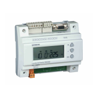
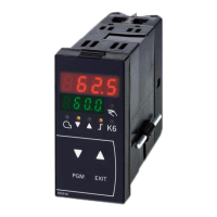
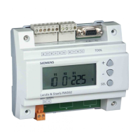
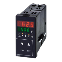
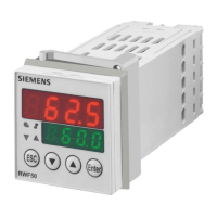
The parameters are shown on the lower setpoint display (green) and their values on the
upper/actual value display (red).
7866z06/0911
Parameter Display Value range
Factory
setting
Remarks
Proportional band ¹
Pb1
1...9999 digit 10 Influences the controller’s P-action
Derivative time
dt
0...9999 s 80
Influences the controller’s D-action
With dt = 0, the controller has no D-action
Integral action time
rt
0...9999 s 350
Influences the controller’s I-action
With rt = 0, the controller has no I-action
Dead band (neutral
zone) ¹
db
0.0...999.9 digit
1
For 3-position output
Y
100%
-100%
db
W
X
7866d13/0911
Controlling element
running time
tt
10...3000 s
15
Running time of the positioning valve for use
with modulating controllers
Switch-on threshold
Heating controller ¹
HYS1
-1999...0.0 digit
-5
Reference!
See chapter 5.2 High-fire operation
Switch-off threshold
stage II
Heating controller ¹
HYS2
0.0...HYS3 digit
3
Reference!
See chapter 5.2 High-fire operation
Switch-off threshold
Heating controller ¹
HYS3
0.0...9999 digit
5
Reference!
See chapter 5.2 High-fire operation
Switch-on threshold
Cooling controller ¹
HYS4
0.0...9999 digit
5
Reference!
See chapter 5.2 High-fire operation
Switch-off threshold
stage II
Cooling controller ¹
HYS5
HYS6...0.0 digit
-3
Reference!
See chapter 5.2 High-fire operation
Switch-off threshold
Cooling controller ¹
HYS6
-1999...0.0 digit
-5
Reference!
See chapter 5.2 High-fire operation
Response threshold
0.0...999.9 0
Reference!
See chapter 5.5 Response threshold
(q)
¹ Setting of decimal place has an impact on this parameter
Note!
When using the RWF50… as a modulating controller only, or as a modulating
controller without the burner release function (1P, 1N), parameter HYS1 must be set to
0 and parameters HYS2 and HYS3 must be set to their maximum values.
Otherwise, for example, when using default parameter HYS1 (factory setting -5), the 3-
position controller is only released when the control deviation reaches -5 K.
Display of controller
parameters
 Loading...
