124 Siemens-Elema AB E382 E380E 061 01 03 01
Diagrams Servo Ventilator 300/300A
8
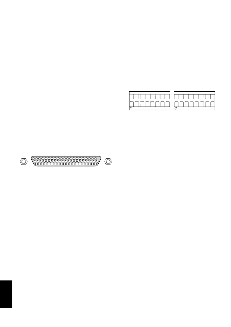
Analog I/O terminal N81
62 pole D-sub connector (N81). Can be used
for connection of monitoring/recording
equipment. Only Siemens connection cable
must be used.
The illustration of the connector show
outside view.
If a signal has three different scale factor
values, e. g. 3/18/45 V/l/s, the different
values refers to selected front panel setting
Adult/Pediatric/Neonate.
Input control signals can be connected at
N81 to control some ventilator functions
(e.g. when using Bi-Phasic Ventilation).
These input signals are routed via two
sockets, J2 and J3, on PC 1587.
300-A17X
21
62
42
1
43
22
N81
1 Chassis GND
2 V- limited; -15 V, max 200 mA, Output
3 0 V (A), Input/Output reference
4 V+ limited; +15 V, max 200 mA, Output
5–
6* Ext press contr lev set in, 0 V – +5 V, Input
7* Ext CMV freq set in, 0 V – +5 V, Input
8* Ext SIMV freq set in, 0 V – +5 V, Input
9* Ext insp time set in, 0 V – +5 V, Input
10 Neb flow buff 3 18 45, 3/18/45 V/l/s, Output
11 Air flow buff 3 18 45, 3/18/45 V/l/s, Output
12 Insp flow buff 3 3 18, 3/3/18 V/l/s, Output
13 Exp flow buff 3 3 18, 3/3/18 V/l/s, Output
14 Insp press buff 50 mV, 50 mV/cm H
2
O, Output
15 Exp press buff 50 mV, 50 mV/cm H
2
O, Output
16 Internal battery voltage lim, Output
17 Insp time buff, 0V ; 5 V, Output
18 Range sel D0 buff, 0V ; 5 V, Output
19 Clock buff 2 H, 0V ; 5 V, Output
20 Patient trig buff H, 0V ; 5 V, Output
21 Serial data to slave buff H, 0V ; 5 V, Output
22 GND, Input/Output reference
23 +5V limited; max 500 mA, Output
24 0V (24), Input/Output reference
25 +24V limited; max 270 mA, Output
26 –
27* Ext press supp lev set in, 0 V – +5 V, Input
28* Ext insp rise time set in, 0 V – +5 V, Input
29* Ext preset min vol set in, 0 V – +5 V, Input
30* Ext pause time set in, 0 V – +5 V, Input
31* Ext CPAP flow set in, 0 V – +5 V, Input
To enable the control functions, jumpers
must be mounted in the sockets. The figure
below, showing sockets J2 and J3, indicates
which connectors that need to be short-
circuited with a jumper to enable a control
signal. (Signal No. as stated in the pin
configuration list below.)
Note – If jumpers are mounted and a
voltage is connected to any of the pin
number marked * in the table below, the
function of the ventilator can be influenced.
32 Airway flow buff 3 3 18, 3/3/18 V/l/s, Output
33 Barometric press buff 4.0, 4.0 V/Bar, Output
34 ET CO
2
conc buff 1.0, 1.0 V/%CO
2
, Output
35 O
2
flow buff 3 18 45, 3/18/45 V/l/s, Output
36 Insp flow patient buff 3 3 18, 3/3/18 V/l/s, Output
37 CO
2
conc buff 1.0, 1.0 V/%CO
2
, Output
38 Serial data to master test H, 0V ; 5 V, Output
39 Range sel D1 buff, 0V ; 5 V, Output
40 Power up reset buff L, 0V ; 5 V, Output
41 Exp time buff, 0V ; 5 V, Output
42 Alarm buff L, 0V ; 5 V, Output
43 –
44 –
45 –
46 –
47* Ext O
2
conc set in, 0 V – +5 V, Input
48* Ext nebulizer time set in, 0 V – +5 V, Input
49* Ext trigg sens set in, 0 V – +5 V, Input
50* Ext PEEP lev set in, 0 V – +5 V, Input
51 Exp flow patient buff 3 3 18, 3/3/18 V/l/s, Output
52 O
2
conc buff 90 mV, 90 mV/%O
2
, Output
53 Insp flow patient buff 7.2 7.2 43.2,
7.2 /7.2/43.2 V/l/s, Output
54 Exp flow patient buff 7.2 7.2 43.2,
7.2 /7.2/43.2 V/l/s, Output
55 Insp press buff 10.7 mV, 10,7 mV/cm H
2
O, Output
56 –
57 –
58 –
59 Serial data to slave test H, 0 V ; 5 V, Input
60 Receive address test L, 0 V ; 5 V, Input
61 Control enable test H, 0 V ; 5 V, Input
62 Receive address buff L, 0V ; 5 V, Output
300-L27X
J3
1234567 8
9
10
111213141516
1234567 8
9
10
111213141516
J2
Signal
No:
29 8 30 9 31
47 48 49 50 27 6 28 7
 Loading...