Supplements to ET 200SP documentation
2.4 I/O module manuals
Product information on the documentation of the ET 200SP distributed I/O system
40 Product Information, 09/2019, A5E03799595-BD
Manual DI 8xNAMUR HF, Edition 02/2014
Section A.2 Parameter assignment and structure of parameter data record
With data records 0 to 7, you can configure individual channels.
When the interface module IM 155-6 DP HF (PROFIBUS DP) is used and data records 0
and 1 are read, the module returns the diagnostics data records and not the parameter data
records of the DI 8xNAMUR HF.
DQ 4x24VDC/2A HS manual, Edition 09/2016
Section 6.1 Technical specifications
For this module, the marine approval for the bridge and deck zone is valid from a bus cycle
time of at least 250 µs.
Manual DQ 4x24..230VAC/2A ST digital output module, Edition 03/2015
Section 3.1 Pin assignment; Supply voltage fuse protection
The module has neither short-circuit protection nor overload protection. Protect the module
from being destroyed by impermissible high current and install a fine fuse in the supply line.
The maximum rated current of the fine fuse depends on the hardware function status (FS) of
the module.
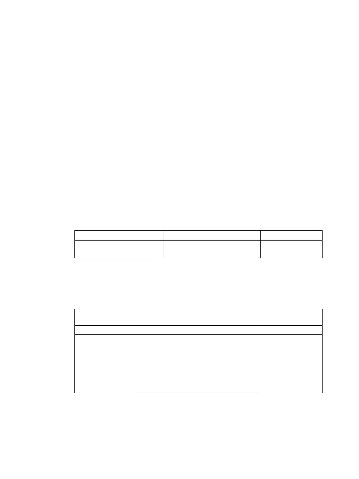
HW functional status of the module
Max. rated current of fuse
Section 6.1 Technical specifications, Switching frequency with inductive load
The switching frequency of the outputs with inductive loads is max. 0.5 Hz.
Higher switching frequency is possible in spite of this, and depends on the alternating
voltage and switched inductors or the power factor of the electric motor used.
Max. switching fre-
quency
200 VAC or higher
• Power factor of the electric motor cos φ > 0.35
• Electric motor must only be turned off after
startup (no jogging mode).
Electric motors which are turned off during
startup could create inductive shutoff voltages
> 600 V , which could destroy the output elec-
10 Hz