Supplements to ET 200SP documentation
2.4 I/O module manuals
Product information on the documentation of the ET 200SP distributed I/O system
Product Information, 09/2019, A5E03799595-BD
41
DQ 4x24..230VAC/2A HF Manual, Edition 02/2018
Section 3.1.1. und 4.1.1 Wiring and block diagram
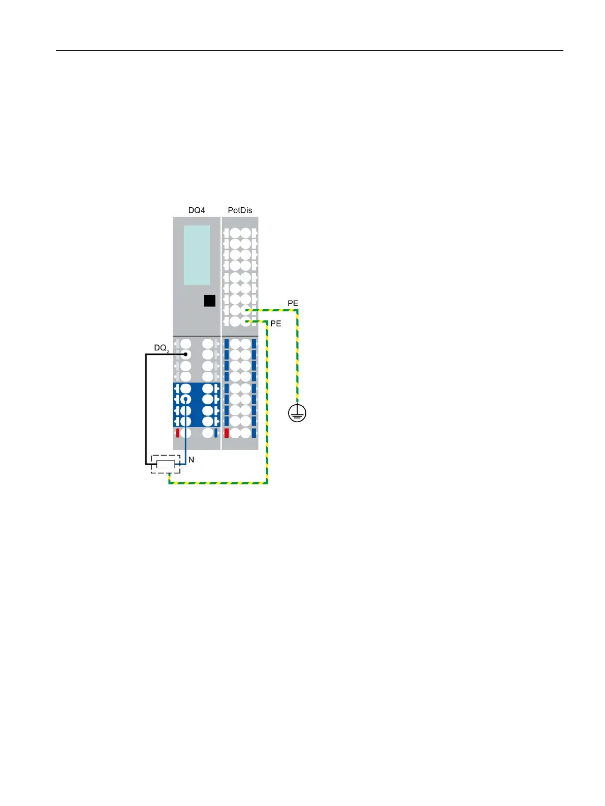
The following figure shows an example for the terminal assignment of the digital output
module DQ 4x24...230VAC/2A HF on the BaseUnit BU type U0 (3-wire connection) in
combination with a potential distribution module and terminal block.
For a 3-wire connection you connect the protective earth (PE) of the actuator to the terminal
block.
Figure 2-2 3-wire connection of actuators with potential distribution module at the digital output
module DQ 4x24...230VAC/2A HF
Equipment manual RQ 4x120VDC-230VAC/5A NO MA ST, Edition 12/2015
Section 3.1 Wiring and block diagram
The AUX terminals of the self-assembling voltage bus can be used for the connection of the
protective conductor (PE) or for voltages up to a maximum of 24 V DC.