Supplements to ET 200SP documentation
2.4 I/O module manuals
Product information on the documentation of the ET 200SP distributed I/O system
Product Information, 09/2019, A5E03799595-BD
45
Communications module IO-Link Master CM 4xIO-Link, Edition 10/2017
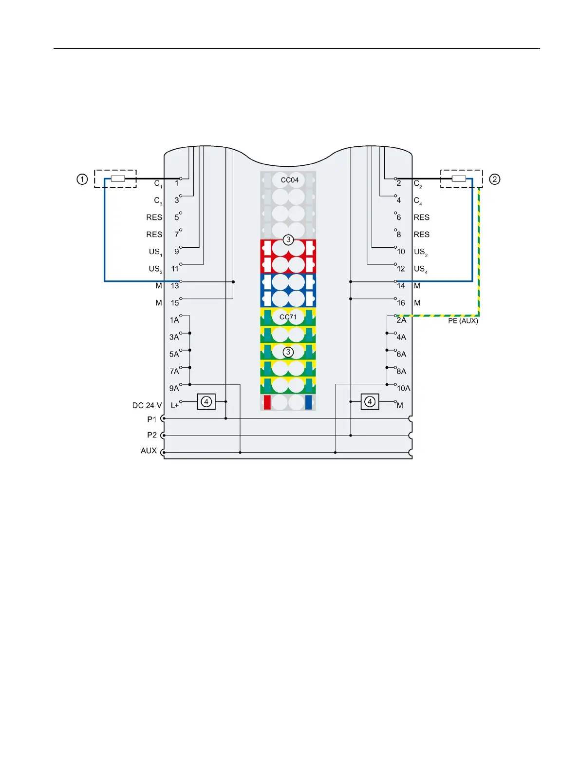
Section Connecting, Wiring and block diagram
Connection: 2-wire and 3-wire connection in DQ operating mode:
Protective conductor connection
Color-coded labels with color code CC04
and CC71 (optional)
P1, P2, AUX Internal self-assembling voltage buses
Connection to the left (dark-colored BaseUnit)
Connection to the left interrupted (light-colored
Filter connection supply voltage (only
when light-colored BaseUnit is present)
C
n
Communication signal, DI, DQ
24 V DC
Supply voltage L+ (infeed for light-colored
RES Reserved, must not be assigned
Supply voltage (positive)
Figure 2-3 Terminal assignment for 2-wire and 3-wire connection in DQ operating mode