Displays and interrupts
7
7.1 Status and error displays
Denition
The LED displays are used as status and error indicators.
Diagnostic messages and maintenance events and their possible causes or remedial measures
are described in the Diagnostic messages and Maintenance events.
Diagnostics alarms (Page 37)
Description
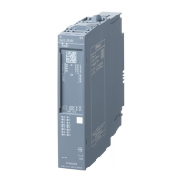
The following gure identies the LED displays of the I/O module.
DIAG MT
DI
HA
8x24..125V DC
7
DI .6 +
8
1
DI .0 +
2
3
DI .2+
4
5
DI .4+
6
1P1
L+
24 VDC
M
1P2
2P1
L+
24 VDC
M
2P 2
MA X. 10 A
.0 .1
V 1.0 .0
CC 42
PW R
6DL1131-6DF0 0-0PK0
X
2
3 4
DI .7+
DI .1+
DI .3+
DI .5 +
DI
15
16
9
10
11
12
13
14
F0 F1
.2 .3
F2 F3
.4 .5
F4 F5
.6 .7
F6 F7
2M
① DIAG LED (Page 24) (green/red)
② MT LED (Page 24) (yellow)
③ Channel status / fault LEDs (Page 25) (green)
④ Channel status / fault LEDs (Page 25) (red)
⑤ PWR LED (Page 25) (green)
DI 8x24...125VDC HA
Equipment Manual, 10/2021, A5E39288633-AD 23

 Loading...


