Installing and Wiring the C7-635
3-11
C7-635 Control System
A5E00155581-04
3.4 Setting Up the Electrical Configuration and Connector Pin
Assignment
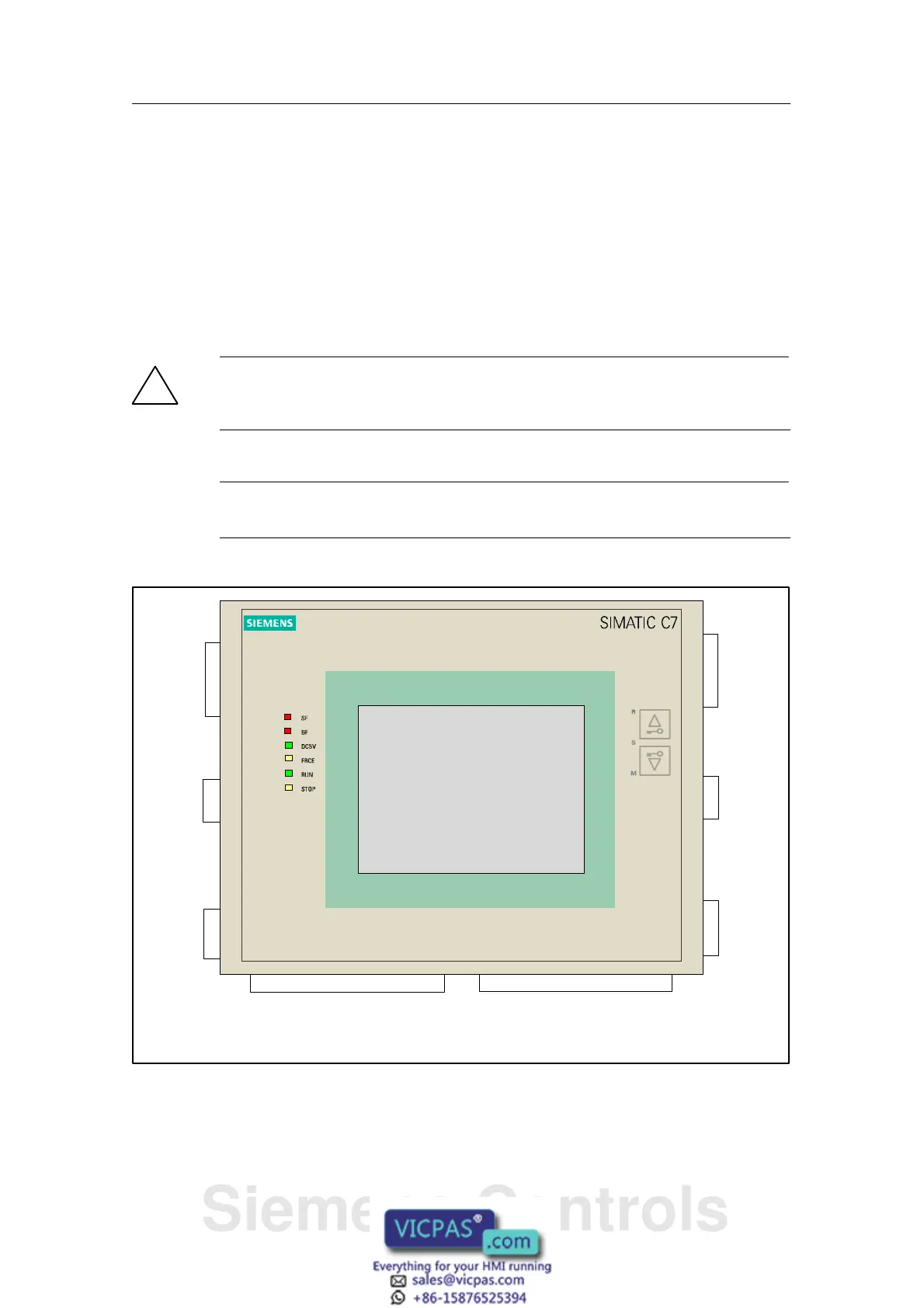
Connector Pin Assignment of the C7-635
Tables 3-2 to 3-10 indicate the connector pin assignment of the C7-635. The
figures show the C7-635 Touch as an example. Connector and socket positions
are identical for the C7-635 Key.
!
Caution
For functional reasons, the connector pin assignment is not compatible with
predecessor products C7-621, C7-623, C7-626, C7-633, and C7-634.
Note
The C7-635 cannot be used in an ungrounded configuration.
I/O connector
DI 16 X 11 in front
DO 16 X 12 in back
Analog
output
AO2
X14
Supply
Connector
X 1
Micro
Memory
Card of
the CPU
X 7
Back-
plane bus
(I/O bus)
X 5 in
back
I/O connector
Supply I/O DI 8 X 10 in front
AI4 + 1 PT100 X 13 in back
Compact
Flash Card
of the TP
X 8
PROFIBU
S/DP
X 3 in front
Program-
ming device
connection
(MPI)
X 2 in back
RS 232
X 4 in front
1
11
1
Figure 3-11 C7-635 Touch with Connectors and Sockets, Front View
Siemens Controls