Special Features of the C7-635
4-5
C7-635 Control System
A5E00155581-04
4.2 Status and Error Displays of the C7-635
Meaning of the Status and Error Displays
The status and error displays are explained in the sequence in which they are
arranged on the C7-635.
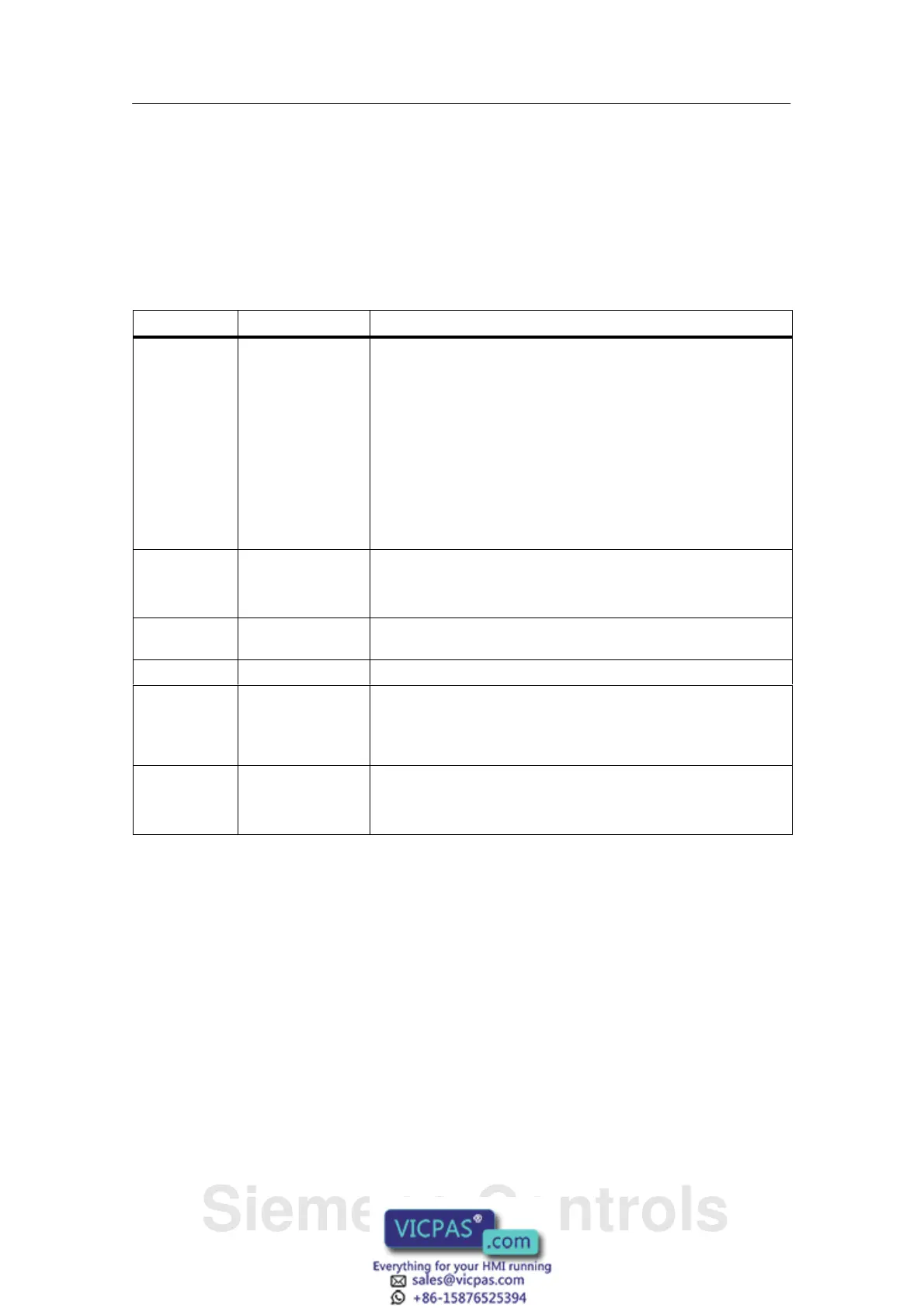
Display Meaning Description
SF (red) C7-635 group error
(SF)
Illuminates if there are:
• Hardware errors
• Firmware errors
• Programming errors
• Parameter assignment errors
• Calculation errors
• Time errors
• I/O errors during internal I/O functions
• For exact error determination, a programming device/PC has
to be used, and the diagnostic buffer has to be read out.
BF (red) Bus error
indication
Illuminates when there are
• bus errors (physical errors)
• DP interface errors
5 VDC (green) 5 VDC supply for
the C7-635
Illuminates if internal 5 VDC supply is okay.
FRCE (yellow) Reserved Illuminates when a force request is active.
RUN (green) RUN mode of the
C7-635
Illuminates when the C7-635 is processing the user program.
Flashes (2 Hz) during the C7-635 startup (in addition, the STOP
display illuminates; after the STOP display goes out, the outputs
are enabled).
STOP (yellow) STOP mode of the
C7-635
Illuminates when the C7-635 is not executing a user program
Flashes slowly when the C7-635 requests a general reset
Flashes rapidly when the C7-635 is performing a general reset.
4.3 Arrangement of additional S7-300 modules
Additional S7-300 Modules
You have the option of connecting up to four additional S7-300 modules to the
C7-635 by means of the S7-300 I/O bus. These modules can be connected either
directly on the device or at a distance of up to 1.5 m.
If you insertan IM-360 interface module, you can use it to connect additional
modules.
You will find a description of how to install S7-300 modules in the S7-300,
CPU 31xC and CPU 31x: Hardware and Installation manual.
Siemens Controls