Installing and Wiring the C7-635
3-20
C7-635 Control System
A5E00155581-04
Analog output X14
For the technological functions, the meaning of the outputs is described in the
column “Analog Positioning”.
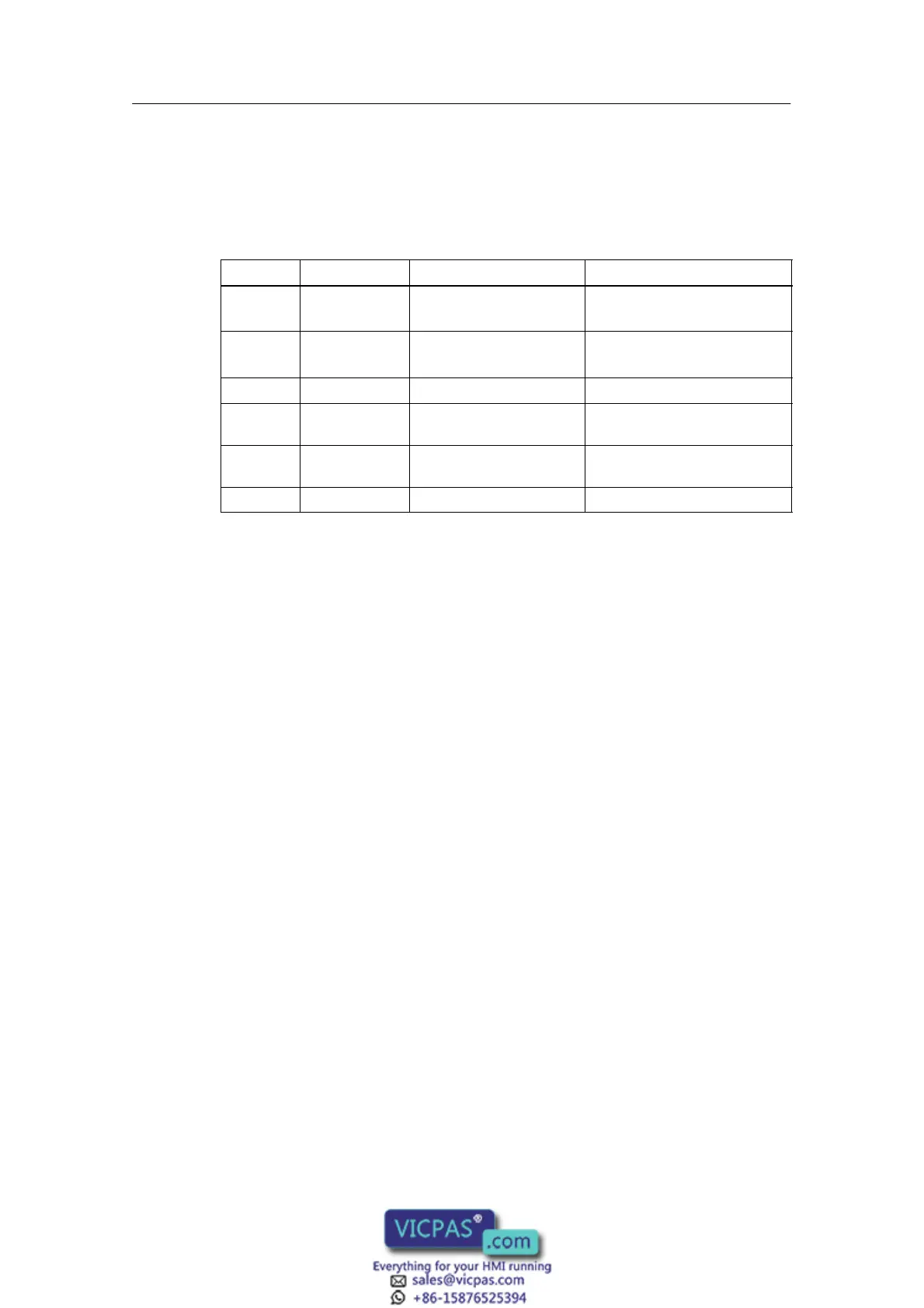
Table 3-10 Connector Pin Assignments Analog Output X 14
Pin Name
Signal Description Analog Positioning
1 AO0_U Analog voltage output
channel 0
Voltage output
Power section
2 AO0_I Analog current output
channel 0
Current output
Power section
3 MANA Analog ground Analog ground
4 AO1_U Analog voltage output
channel 1
–
5 AO1_I Analog current output
channel 1
–
6 MANA Analog ground Analog ground