Installation
8-8
TP 070 Equipment Manual
Release 03/00
8.2.2 Connect PLC
Connection configuration
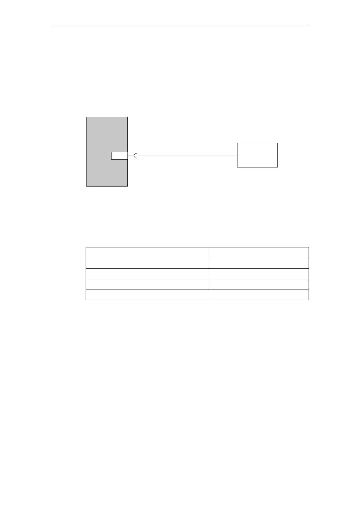
Figure 8-3 illustrates the basic connection possibilities between the operating unit
and PLC. The connection displayed is established by means of a PC-PPI cable.
1)
Only use approved cables for connection to the SIMATIC S7.
Operating unit
IF1B
RS485
SIMATIC
S7–200
1)
Figure 8-3 Connection configuration for PLCs
The following components have been approved for connecting the TP 070 to the
SIMATIC S7:
MPI cable Order no.: 6ES7901–0BF00–0AA0
SINEC L2 bus terminal RS485 Order no.: 6GK15000–0A_006
SINEC L2 bus connector (even) Order no.: 6GK15000–0EA00
SINEC L2 bus connector (curved) Order no.: 6ES7972–0B20–0XA0
SINEC L2 FO bus terminal Order no.: 6GK15000–1A_00
’_’ = Length code