Installation and commissioning
3.2 Procedure for installation and commissioning
CP 343-1 ERPC
18 Manual, 03/2010, C79000-G8976-C239-02
Step Execution Meaning / explanation
7 Optional:
complete the ILS Workbench configuration
and download this to the CP.
This step is only necessary if you want to use ERPC functions.
Read the relevant documentation of our cooperation partners
ILS Technology LLC.
8 Use the diagnostic functions during
commissioning and to analyze problems.
The following options are available:
The LED displays on the CP
Hardware diagnostics and troubleshooting with STEP 7
Communication diagnostics with STEP 7 / NCM
Diagnostics
Static information using HW Config
Web diagnostics
If applicable, evaluation of the alarm block FB54 in the user
program
Queries via SNMP
1
2
3
4
5
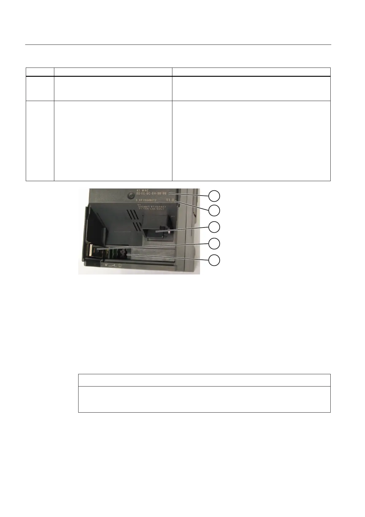
Figure 3-1 CP connectors with the front panel open
1 MAC address
2 Firmware version
3 LAN connector P1 (RJ-45 jack)
4 Chassis ground slider (see below for description)
5 Connecting the power supply
Ground/chassis ground concept
NOTICE
Please note the instructions regarding the grounding and chassis ground concept in the
SIMATIC S7 installation guides; see “SIMATIC S7 Programmable Controller S7300 -
Installation and Hardware: Installation Manual" /10/.
Behind the hinged panel on the left of the device, you will see a slider with which you can
connect or disconnect the chassis ground of the 24 V power supply with reference ground.
 Loading...


