Description of the device
4.7 LED display
SCALANCE XM-400
32 Operating Instructions, 09/2018, C79000-G8976-C306-08
Using the fault mask, you specify an individual "good status" for the connected ports and the
power supply. Deviations from this status are displayed as errors/faults.
To define the fault mask, follow the steps below:
1. Switch to display mode D.
Display mode D is active if the "DM1" and "DM2" LEDs are lit green..
If another display mode is active, you will need to press the "SET/SELECT" button
repeatedly until the "DM1" and "DM2" LEDs are lit green.
2. Hold down the "SELECT/SET" button for 5 seconds.
After 2 seconds,the "DM1" and "DM2" LEDs start to flash for 3 seconds. At the same
time, the port LEDs go on one after the other.
After you have held down the button for 5 seconds, the current settings are stored as the
"good status".
If you release the button before the 5 seconds have elapsed, the previous fault mask will
be retained.
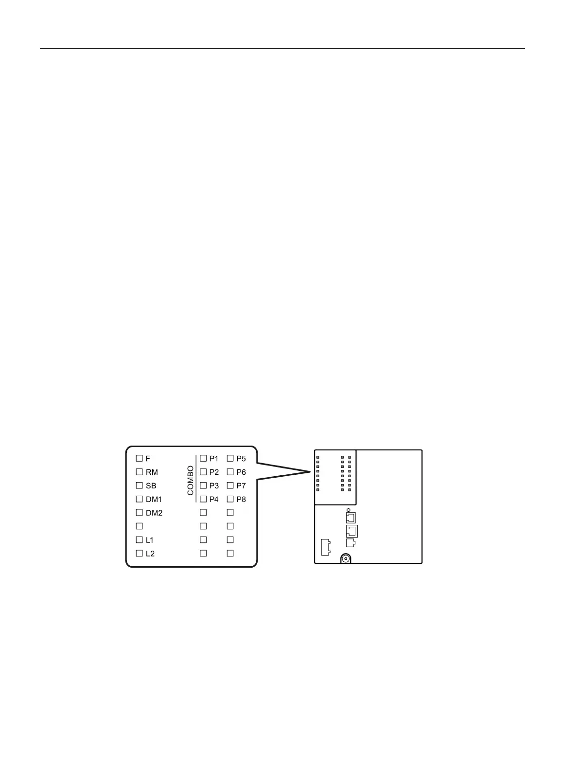
The following figure shows the arrangement of the LEDs.
LED for displaying the fault/error status
LED for displaying the "redundancy manager" function
LED for display of redundantly linked rings
LEDs for displaying the display mode
LEDs for displaying the power supply
LEDs for displaying the port status *)
Indicates that the LEDs belong to combo ports
*
)
The number of port LEDs depends on the device.
 Loading...