Connecting
7.6 Connecting the J1939 bus
SIMATIC PN/J1939 LINK
Operating Instructions, 12/2018, A5E45307564-AA
41
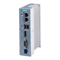
PN/J1939 LINK is connected to the J1939 network
via an adapter cable with DSUB connector (9-pin,
female) ①. Use a shielded CAN cable conforming
to CiA specifications with shielded connector for the
connection.
The physical data transmission is performed via a CAN interface according to
ISO 11898-2 (high-speed).
The following figure shows the assignment of the 9-pin DSUB connector on the
PN/J1939 LINK.
J1939 connector pin
assignment
1 -- Terminating resistor 120 Ω (install jumper from pin
CAN_L bus cable (dominant low)
7 CAN_H CAN_H bus cable (dominant high)
EMC stability is only guaranteed with shielded CAN cables.
 Loading...